
Covering material for solar thermal power generating system and solar thermal power generating system formed by spreading the covering material

a technology of solar thermal power generation system and covering material, which is applied in the direction of solar radiation prevention, wind motors, machines/engines, etc., can solve the problems of large area, large cost of such a replacement work of the roof of the heat collector, and significant decrease in power generation quantity. , to achieve the effect of excellent transparency, excellent power generation efficiency and high tensile yield strength

Active Publication Date: 2008-02-05
ASAHI GLASS CO LTD
View PDF21 Cites 20 Cited by
  • Summary
  • Abstract
  • Description
  • Claims
  • Application Information

AI Technical Summary

Benefits of technology

[0012]The covering material for solar thermal power generation system of the present invention, has high tensile yield strength enabling to widen the interval of support-structures in the heat collector, and the covering material is excellent in transparency and provides excellent power-generation efficiency. Further, since the material is excellent in weather-resistance, it is not necessary to be replaced for a long time, which reduces maintenance cost. Further, by employing a wide-width film obtained by fusion-bonding, the heat collector can be covered efficiently. Further, by attaching a cable at the end of the film, the heat collector can be covered efficiently and easily.

Problems solved by technology

Wind power generation has already been practically used in Europe and Asia, but it has a problem that power-generation quantity significantly decreases when wind speed decreases.
However, it has a problem that sufficient solar energy can not be obtained when sun light is prevented by cloud.
In a case where a material having insufficient weather-resistance is used as a covering material for a heat collector of a solar chimney which is intended to supply electric power almost permanently, periodic replacement is required and cost for such a replacing work of a roof of the heat collector having a large area, becomes high.
As a result, there is a problem that power-generation cost is increased.
Therefore, when a material having insufficient mechanical strength is employed, support-structures have to be installed at a small interval, which causes a problem that solar light is blocked by such support-structures to reduce power-generation efficiency.
On the other hand, in a case where a glass excellent in weather-resistance and mechanical strength, is employed, thick support-structures have to be provided at a small interval to support the weight of the glass, which causes a problem that solar light is blocked to reduce power-generation efficiency.

Method used


Image

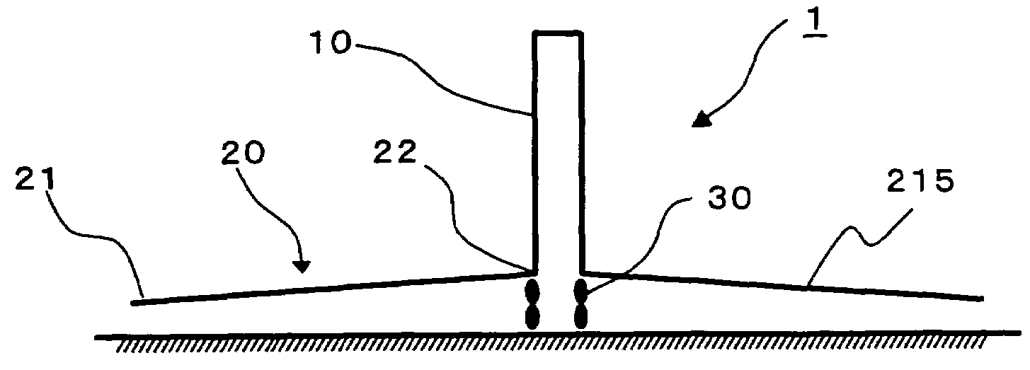
  • Covering material for solar thermal power generating system and solar thermal power generating system formed by spreading the covering material
  • Covering material for solar thermal power generating system and solar thermal power generating system formed by spreading the covering material
  • Covering material for solar thermal power generating system and solar thermal power generating system formed by spreading the covering material

Examples


example 1

Example of Preparing a Film

[0081]ETFE was prepared by a solution polymerization method described in JP-A-6-157616. The copolymerization composition of the ETFE, was that monomer units based on tetrafluoroethylene / monomer units based on ethylene / monomer units based on CH2═CHC4F9=52.4 / 46.4 / 1.2 (molar ratio). The ETFE was molded by using a melt extruder with a T-shaped die, at a die-temperature of 300° C. to produce a film of 100 μm in thickness. The tensile yield strength, the solar radiation transmittance and the weather resistance of the ETFE film obtained, were measured. The results are shown in Table 1.

example 2

Example of Preparing a Wide Film

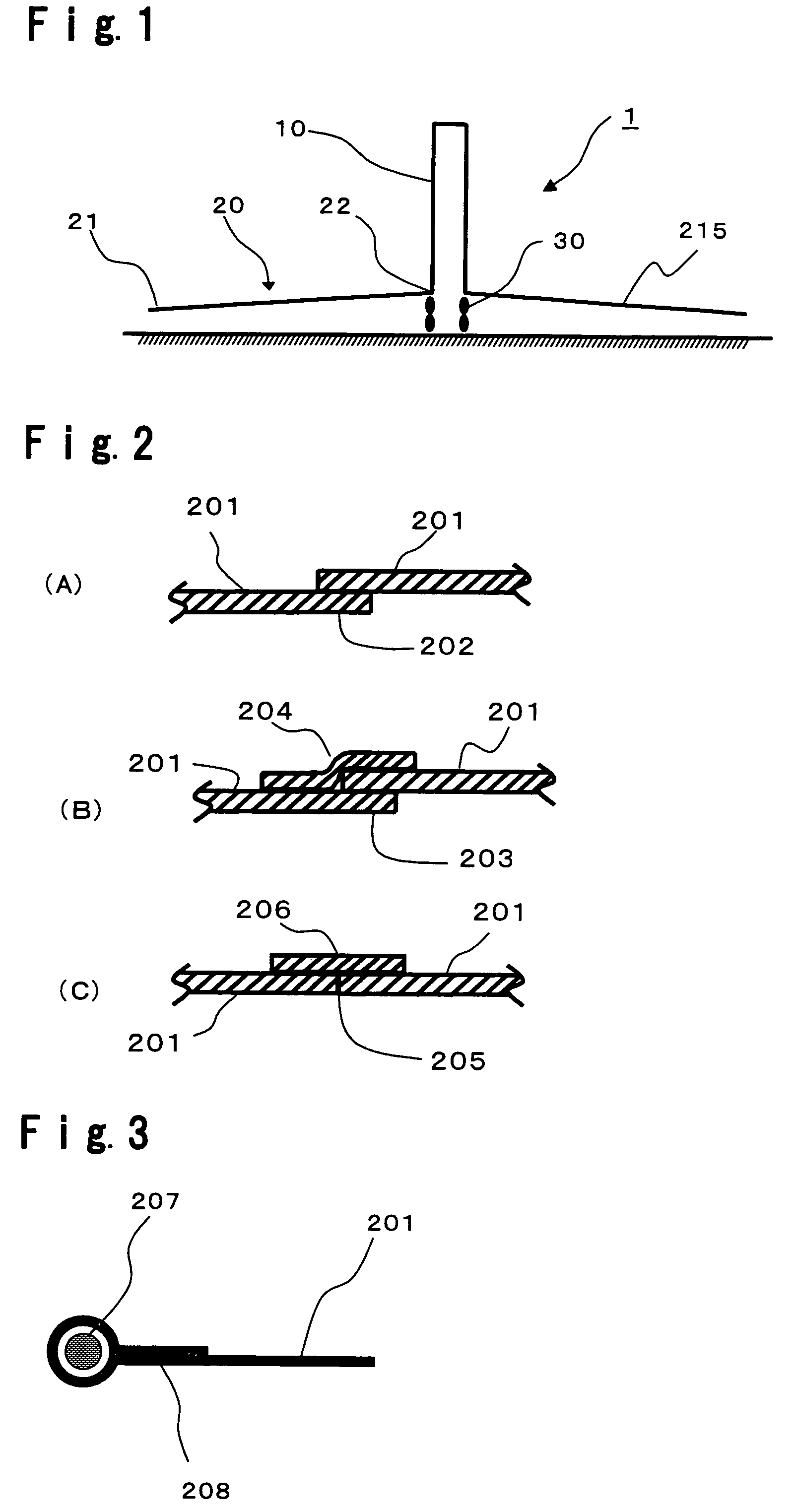
[0084]Two ETFE films having a width of 130 cm obtained by Example 1, were fusion bonded at a fusion-bonding temperature of 260° C. by using a thermal fusion bonder (manufactured by Queen Light Electronic Industries Ltd., Heat Sealer LHP-W705). This step was repeated to produce a large-width film having a width of 5 m. An ETFE film A was obtained by simply overlapping and fusion bonding portions within 3 cm from the ends of films (fusion-bonded portion of FIG. 2(A)). An ETFE film B was obtained by overlapping portions within 1 cm from the ends of films, and further overlapping a reinforcement film of 3.5 cm wide on the overlapping portion (the fusion-bonded portion of FIG. 2 (B)). An ETFE film C was obtained by butting the ends of films, overlapping a reinforcement film of 3.5 cm wide on the batted portion so as to bridge the butted portion, and fusion bonding the portion (fusion-bonded portion of FIG. 2(C)). Cross sections of the fusion-bonded portion...

example 3

Construction of a Solar Thermal Power Generation System

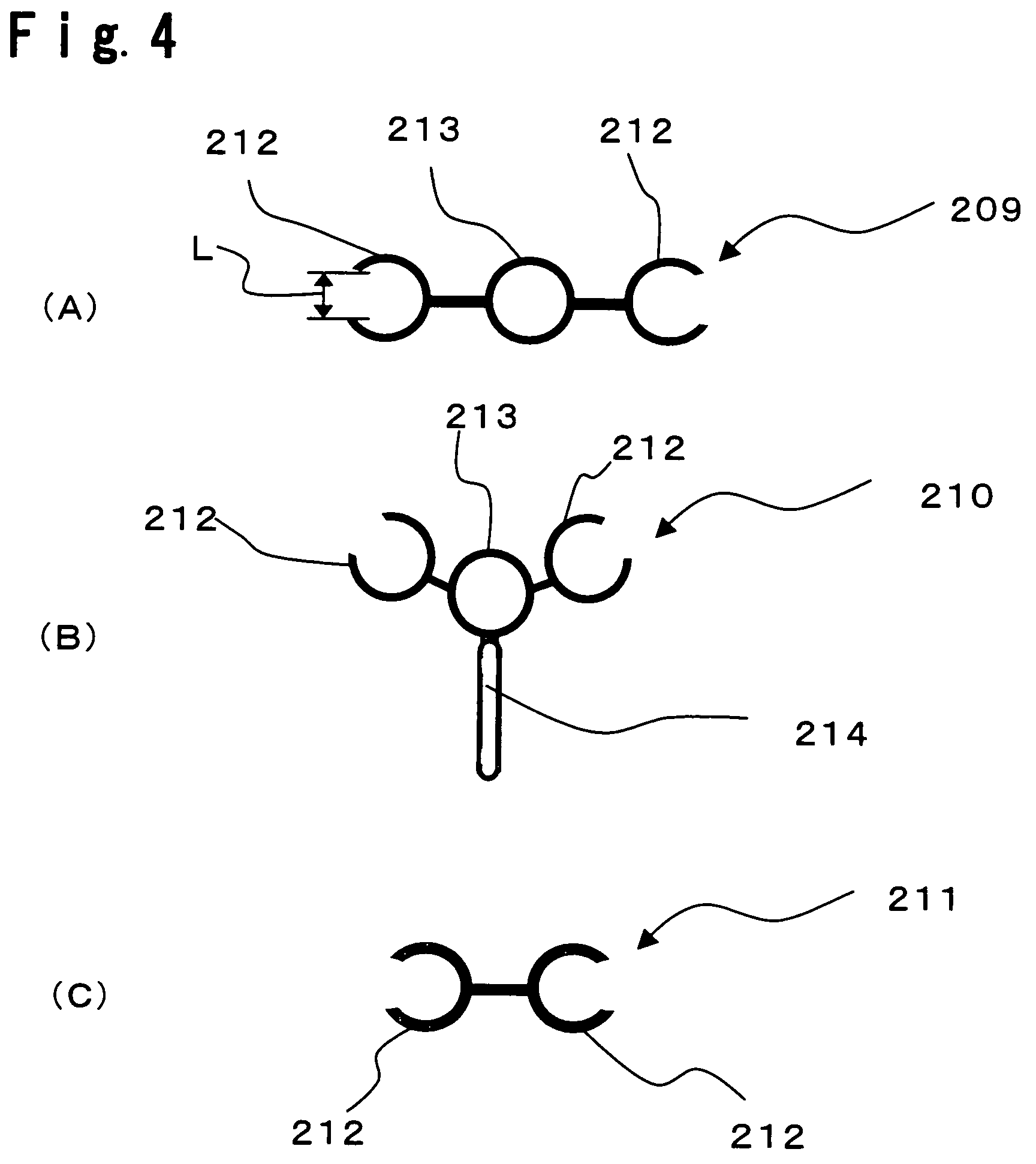
[0085]A cable (PVA cable) made of polyvinyl alcohol resin having a diameter of 1 cm was attached to the end of a ETFE film. Specifically, the peripheral portion of the ETFE film was folded so as to wrap the PVA cable to accommodate the PVA cable. Surfaces of the peripheral portion of the ETFE film folded in a loop shape were fusion-bonded to fix the PVA cable to the end of the film, to prepare a ETFE film having a PVA cable attached to its end. The cross section of the end of the ETFE film having a PVA cable attached to its end, is shown in FIG. 3. Then, using a connecting jigs, the ETFE film having a PVA cable attached to its end, was inserted into a connecting jig 209 and a connecting jig 210. The connecting jig 209 is fixed to a support-structural member, and the ETFE film covers the support-structural member and poles. A tension wire is let through a ring for letting tension wire, of the connecting jig 210. By pulling the co...


PUM

PropertyMeasurementUnit
solar radiation transmittanceaaaaaaaaaa
tensile yield strengthaaaaaaaaaa

Abstract

A covering material for solar thermal power generation system, characterized in that it is made of a film which has a tensile yield strength of at least 10 N / mm2 according to JIS K7127, a solar radiation transmittance of at least 85% according to JIS R3106, and a retention of at least 80% against the initial value of the tensile breakage strength after 5000 hours of the sunshine carbon arc lamp weather test according to JIS B7753.

Description

TECHNICAL FIELD[0001]The present invention relates to a covering material for solar thermal power generating system and a solar thermal power generating system formed by spreading the covering material. In more detail, the present invention relates to a covering material for solar thermal power generating system, which is excellent in mechanical strength, transparency and weather-resistance, and to a solar thermal power generating system formed by spreading the covering material.BACKGROUND ART[0002]In recent years, power generating methods for generating clean and renewable energy have been progressed to cope with fear of exhaustion of oil energy and environmental problem. As representative examples, wind power generation and solar-light-condensing power generation are mentioned. Wind power generation has already been practically used in Europe and Asia, but it has a problem that power-generation quantity significantly decreases when wind speed decreases. Further, in the solar light...

Claims


Application Information

Patent Timeline
Patent Type & Authority Patents(United States)
IPC IPC(8): F03G6/00C08J5/18F24J2/50
CPCF03D9/007F03G6/045F24J2/50F05B2240/131Y02E10/465Y02E10/72F03D9/35F03D9/37F24S80/50Y02E10/46Y02E10/728
Inventor MOMII, TATSUOSHIRATORI, SATOSHI
Owner ASAHI GLASS CO LTD
Learn More