
Hammer for a material size reduction machine

a technology of material size and hammer, which is applied in the direction of grain treatment, etc., can solve the problems of regular replacement of damaged or worn hammers, and achieve the effects of strong secondary breakage, higher grinding efficiency, and favorable impact wear characteristics

Inactive Publication Date: 2008-02-05
ARVOS RAYMOND BARTLETT SNOW LLC
View PDF12 Cites 42 Cited by
  • Summary
  • Abstract
  • Description
  • Claims
  • Application Information

AI Technical Summary

Benefits of technology

The design provides improved impact wear characteristics, increased grinding efficiency, and uniform wear distribution, extending the hammer's service life and maintaining peak performance.

Problems solved by technology

One problem associated with such machines is the regular need to replace damaged or worn hammers, this need being engendered by the high rates of rotation and the impact energies associated with the contact of the hammers with the particulate material to be size reduced.

Method used


Image

  • Hammer for a material size reduction machine
  • Hammer for a material size reduction machine
  • Hammer for a material size reduction machine

Examples


Embodiment Construction

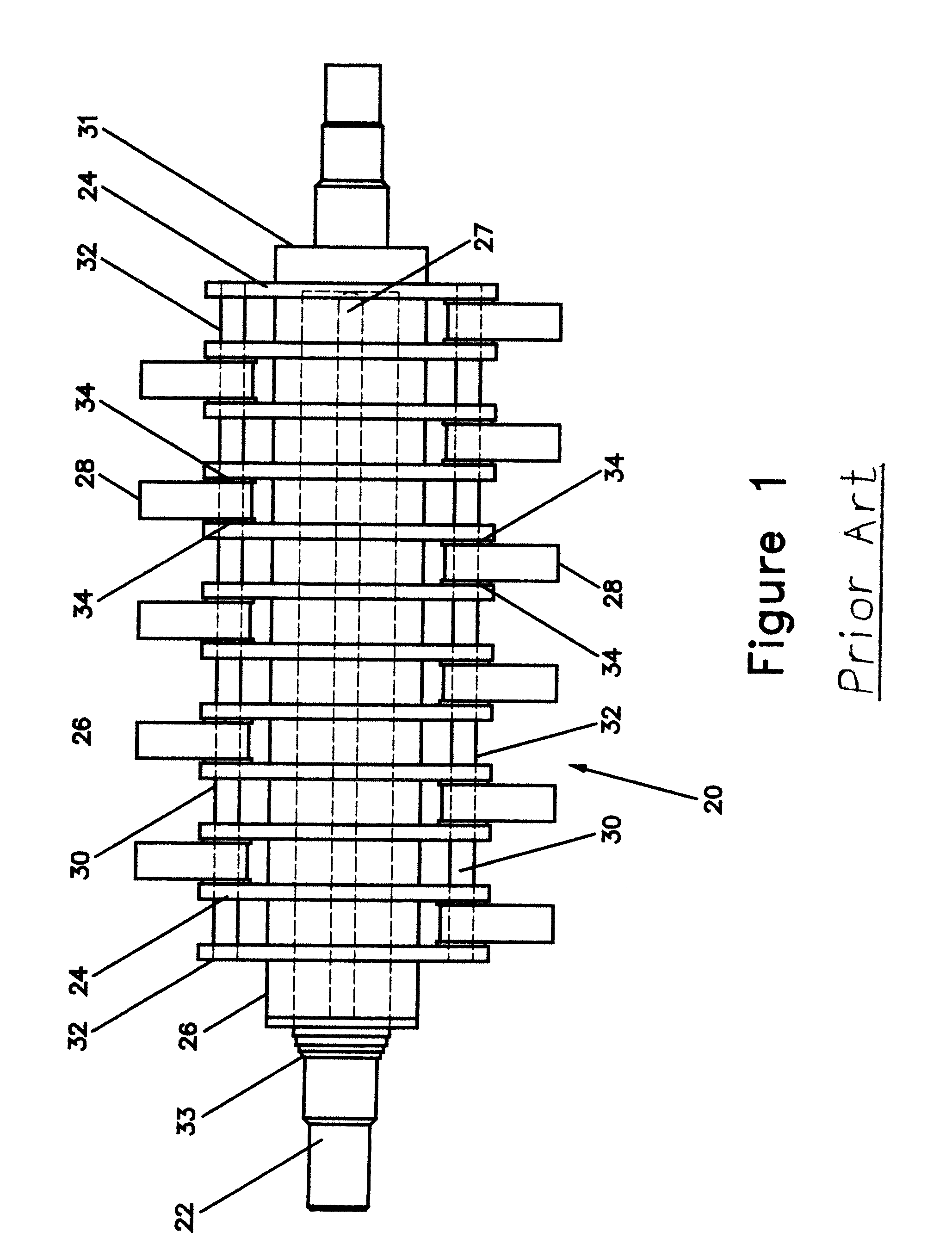
[0016]Referring now to the drawings, FIG. 1 illustrates a conventional hammermill suitable for use with the hammer of the present invention. This conventional hammermill is illustrated and described in U.S. Pat. No. 5,507,441, wherein, in that FIG. 1 of that patent and as illustrated in FIG. 1 herein, there is illustrated a hammermill 20 having a main shaft 22 which is rotated about a longitudinal axis by conventional driving mechanisms such as gas or electric powered motors. Mounted in longitudinally spaced relation along the shaft 22 are a plurality of plates 24. Associated with the plates 24 are a plurality of hubs 26 for maintaining spacing of the plates 24 along the shaft 22. The plates 24 each have keyways which mate with a longitudinally extended key 27 formed by the main shaft 22 for preventing relative rotation between the shaft 22 and the plates 24. The plates 24 and hubs 26 are prevented from moving longitudinally along the main shaft 22 by an end plate 31 rigidly connect...


PUM


Abstract

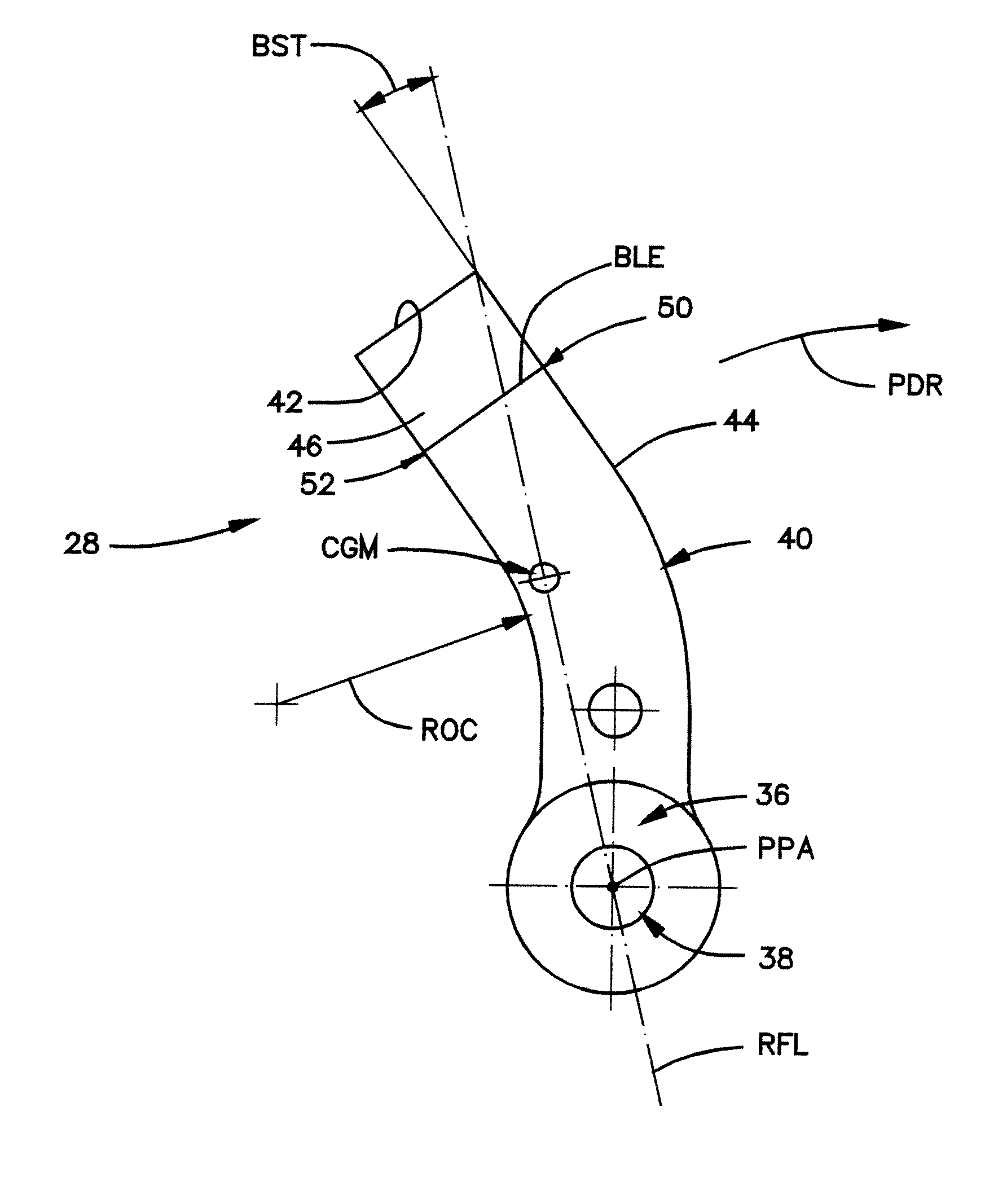
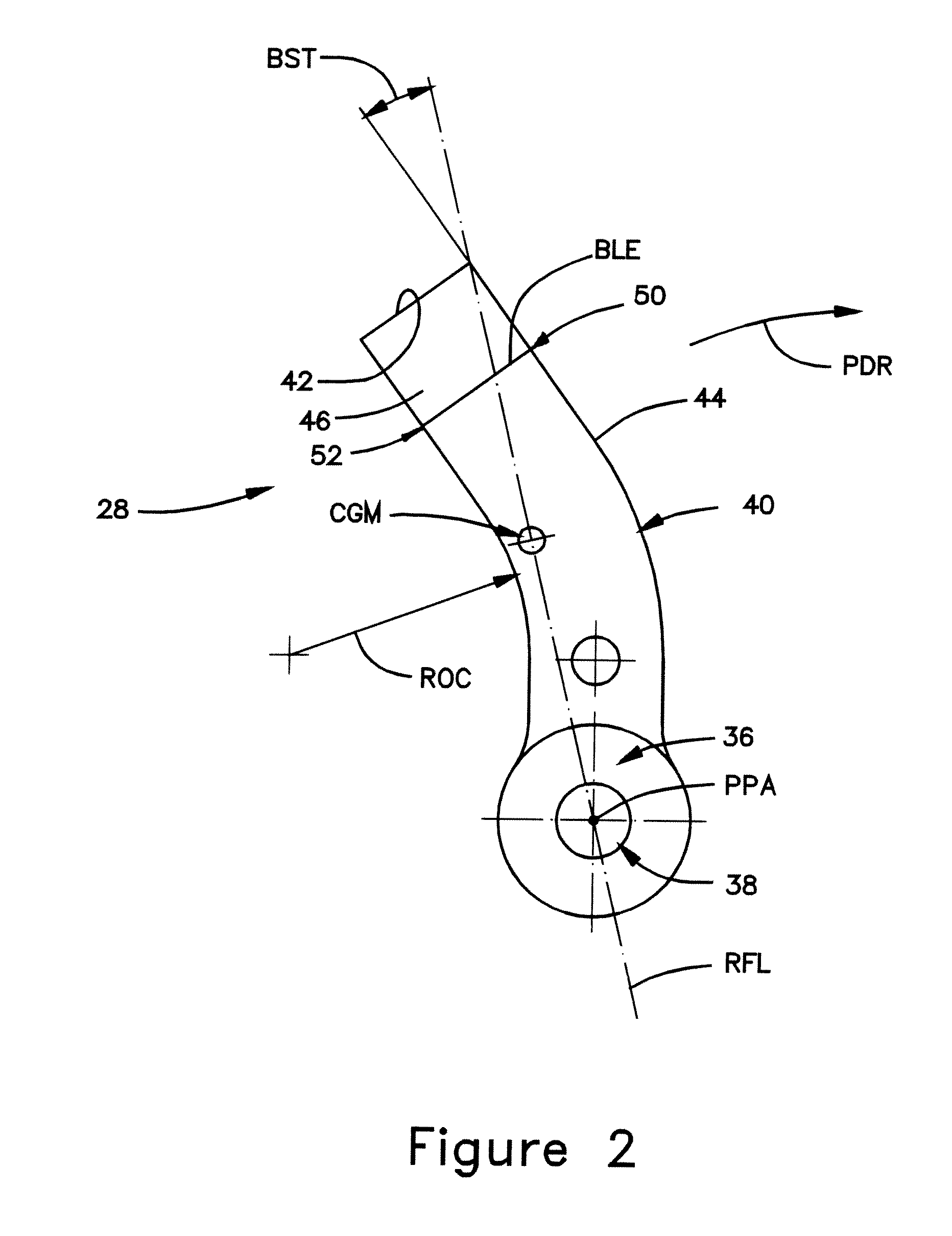
A hammer 28 is provided for a material size-reducing machine of the type including a rotor on which the hammer is individually pivotally mounted. The hammer 28 includes a mounting end 36 having a throughbore for receiving a pivot pin therethrough in connection with the pivot mounting of the hammer on the rotor, an extending portion 40 with the center of mass CGM located therein. The extending portion has a non-linear body portion 44 and a linear body portion 46 with the linear body portion 46 being inclined in a direction opposite to the rotation direction at an angle between 5 to 45 degrees as measured relative to a line RFL extending through the center of the pivot pin and the center of mass CGM of the hammer.

Description

BACKGROUND OF THE INVENTION[0001]The invention relates to a hammer for a material size reduction machine.[0002]Typically, in conventional hammer mills, a large number of hammers are individually pivotally mounted on a rotating drum or disk rotating at high speed. The hammers are rotated at high speed and sweep adjacent the inner circumferential wall of a mill housing, whereupon particles to be size reduced are fed into the mill and collide with the front faces of the hammers.[0003]To achieve a desired high output, and because of the wide variety of materials that must be processed by these material size reducing machines, the hammer mills or rotors must be very heavily constructed to provide the necessary strength for effective operation and durability. Additionally, a heavy hammer mill or rotor will also have a large amount of angular momentum and energy to effectively process tough, high strength materials and also maintain a relatively constant rotational speed, resulting in less...

Claims


Application Information

Patent Timeline
Patent Type & Authority Patents(United States)
IPC IPC(8): B02C13/00B02C13/28
CPCB02C13/28B02C2013/2808
Inventor CHEN, MICHAEL MING-MINGCHEN, JIANRONGPODMOKLY, DAVID MICHAEL
Owner ARVOS RAYMOND BARTLETT SNOW LLC
Learn More