Vehicle rear body structure

a rear body and rear body technology, applied in the direction of roofs, transportation items, transportation and packaging, etc., can solve the problems of increased and achieve the effect of increasing labor in manufacturing and difficulty in maintaining the form accuracy of partition panels

Active Publication Date: 2008-02-05
NISSAN MOTOR CO LTD
View PDF12 Cites 17 Cited by
  • Summary
  • Abstract
  • Description
  • Claims
  • Application Information

AI Technical Summary

Benefits of technology

[0005]In the aforementioned vehicle rear body structure, the partition panel at the rear of the rear seat is formed of a large single panel member. The V-shaped reinforcing bead formed on the indented surface extends to a peripheral edge portion of the partition panel, and gives the peripheral edge portion in a complicated shape formed of a large number of plane elements crossing one another. Therefore, it is difficult to maintain the form accuracy of the partition panel when it is attached to a position. Accordingly special care has to be taken in task sequence and accuracy control, resulting in increased labor in manufacturing.
[0006]It is an object of the invention to provide a vehicle body structure at the rear of a rear seat of a vehicle, which allows the form accuracy of the respective members to be kept easily and rigidity of the vehicle body to be improved while saving the effort in the manufacturing.

Problems solved by technology

Therefore, it is difficult to maintain the form accuracy of the partition panel when it is attached to a position.
Accordingly special care has to be taken in task sequence and accuracy control, resulting in increased labor in manufacturing.

Method used


Image

  • Vehicle rear body structure
  • Vehicle rear body structure
  • Vehicle rear body structure

Examples


Embodiment Construction

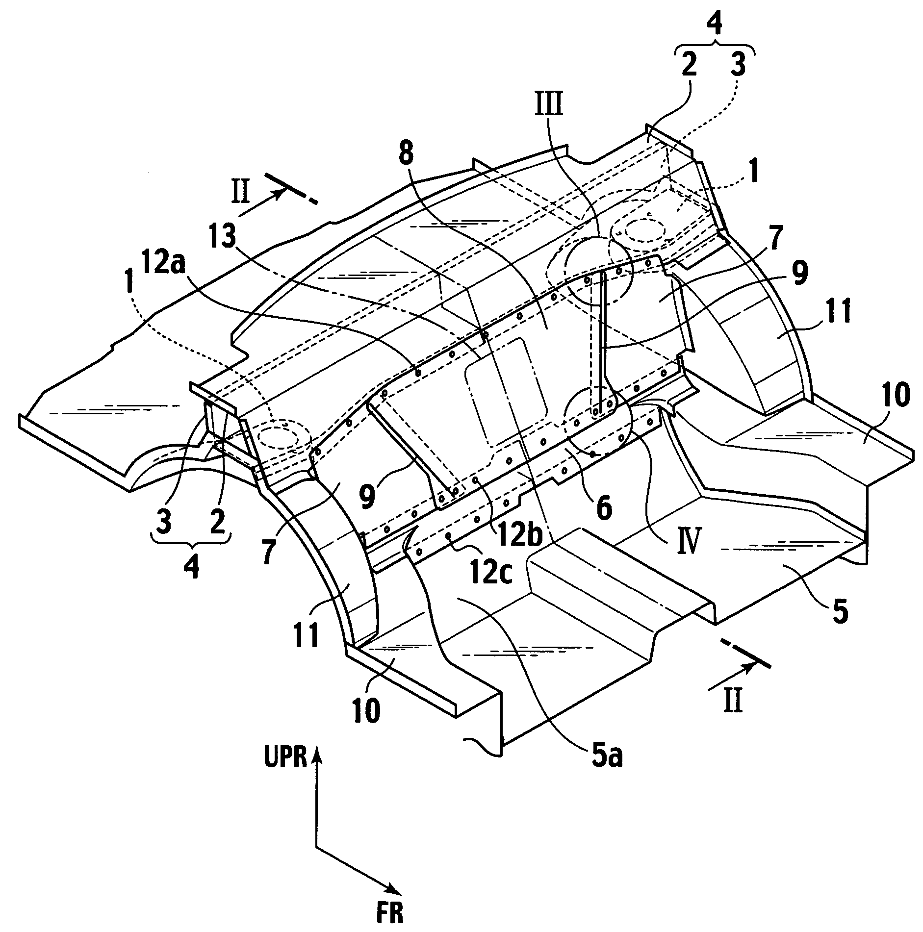
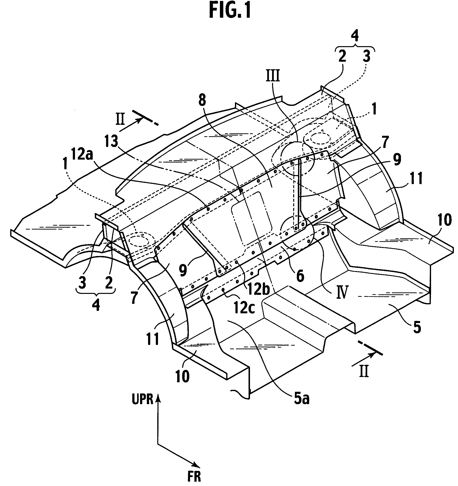
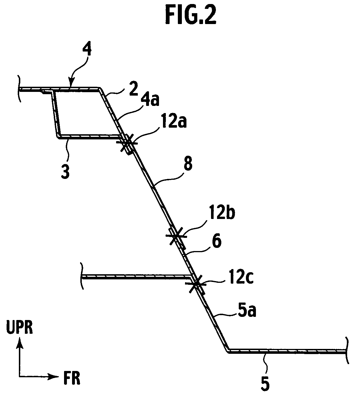
[0015]An embodiment of the present invention will be explained below with reference to the drawings, wherein like members are designated by like reference characters. In the drawings, UPR represents a direction upward of the vehicle, and FR represents the front side in the longitudinal direction of the vehicle.

[0016]In a vehicle rear body structure according to the embodiment of the present invention, a box-section cross member 4 (hereinafter referred to as a parcel member 4) is provided beneath a rear parcel shelf to connect upper ends of rear suspension towers 1 (or strut towers) on both side rears of the vehicle body. The parcel member 4 is formed of a panel member 2 (hereinafter referred to as a parcel 2) extending in the vehicle transverse direction, having an L-shape in section including a horizontal upper wall and a front wall extending downward from a front edge of the upper wall, and a reinforcement panel member 3 (hereinafter referred to as a reinforcement parcel 3) attach...


PUM


Abstract

A vehicle rear body structure including: a cross member provided beneath a rear parcel shelf to connect upper ends of rear suspension towers; a strip member provided along a rear edge of a floor panel; and panel members provided between the cross member and the strip member to connect the cross member and the strip member. The panel members include a center panel and a pair of side panels arranged on outer sides in a vehicle transverse direction of the center panel, respectively. Each of the side panels is joined along an inner edge in the vehicle transverse direction thereof to the center panel by a continuous welding.

Description

BACKGROUND OF THE INVENTION[0001]1. Field of Invention[0002]The present invention relates to a vehicle rear body structure, and more particularly, to a vehicle body structure at the rear of a rear seat of a vehicle.[0003]2. Description of Related Art[0004]Japan Patent Application Laid-Open Publication No. 2000-229584 discloses a vehicle rear body structure in which a partition panel is provided at the rear of a rear seat for separating a passenger compartment from a rear space of the vehicle. The partition panel has an indented surface with a reinforcing bead in a V-shaped pattern as viewed from the front.SUMMARY OF THE INVENTION[0005]In the aforementioned vehicle rear body structure, the partition panel at the rear of the rear seat is formed of a large single panel member. The V-shaped reinforcing bead formed on the indented surface extends to a peripheral edge portion of the partition panel, and gives the peripheral edge portion in a complicated shape formed of a large number of p...

Claims


Application Information

Patent Timeline
Patent Type & Authority Patents(United States)
IPC IPC(8): B62D25/08
CPCB62D21/152B62D25/08
Inventor YAMAZAKI, AKIHITO
Owner NISSAN MOTOR CO LTD
Why Eureka
Try Eureka