System, clamping element and counter-element for the connector of profiled elements

Inactive Publication Date: 2008-02-05
BASLER NORBERT
View PDF24 Cites 3 Cited by
  • Summary
  • Abstract
  • Description
  • Claims
  • Application Information

AI Technical Summary

Benefits of technology

[0006]Taking this prior art as the departure point, the object of the invention is to provide a system, a clamping element and a locking element for connecting profile elements by means of which maximum levels of adjustability and specific load-bearing capacity and low outlay during the production and assembly of, as far as possible, commercially available profiles is possible.

Problems solved by technology

The disadvantage of all the known designs is the need for producing the recesses in the profiles or uprights, use being made of customary production methods such as punching, drilling or milling.
In general, such load-bearing structures with periodically repeating recesses cannot be adjusted with the desired precision.

Method used


Image

  • System, clamping element and counter-element for the connector of profiled elements
  • System, clamping element and counter-element for the connector of profiled elements
  • System, clamping element and counter-element for the connector of profiled elements

Examples


Embodiment Construction

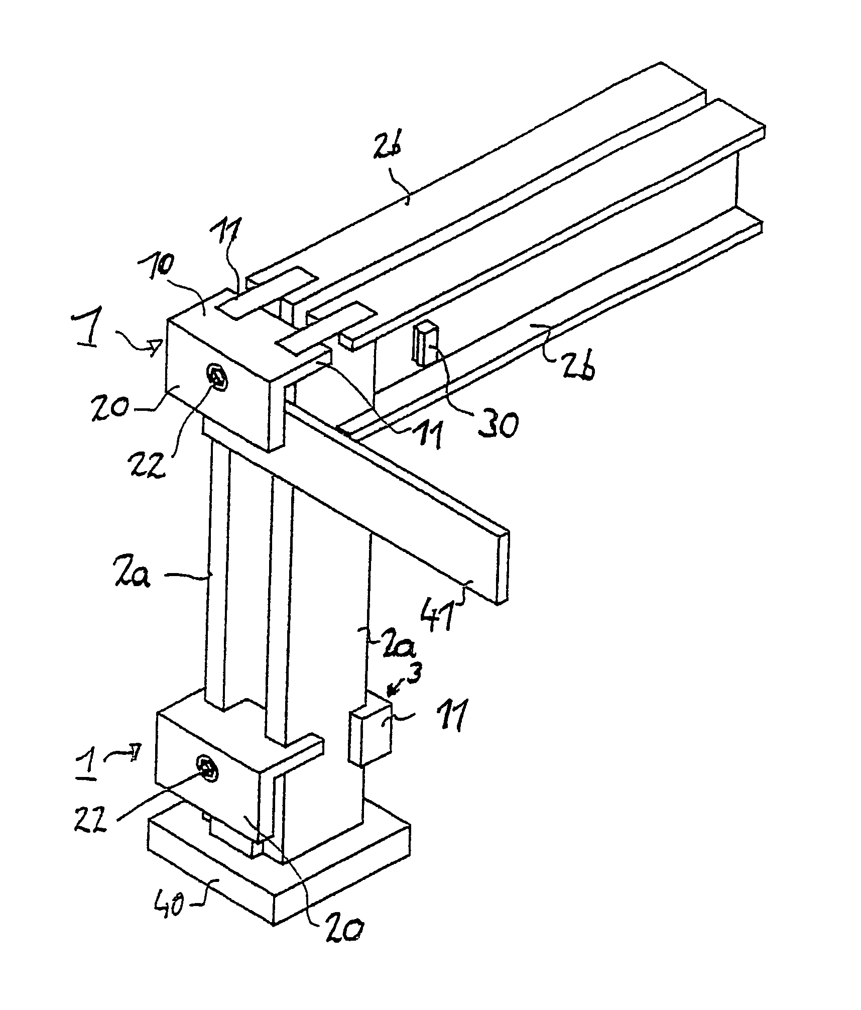
[0054]FIG. 1 shows a system for connecting profile elements 2 via a clamping element 1, which interacts with a locking element 3 via devices for bracing the clamping element 1 with the locking element 3. The detail of a table or of a trestle which is illustrated here shows two profile elements 2a which are designed as panels or rails with a rectangular cross section. These profile elements 2a are arranged separately and extend vertically in the longitudinal direction in order to form a corresponding upright or a table leg or support.

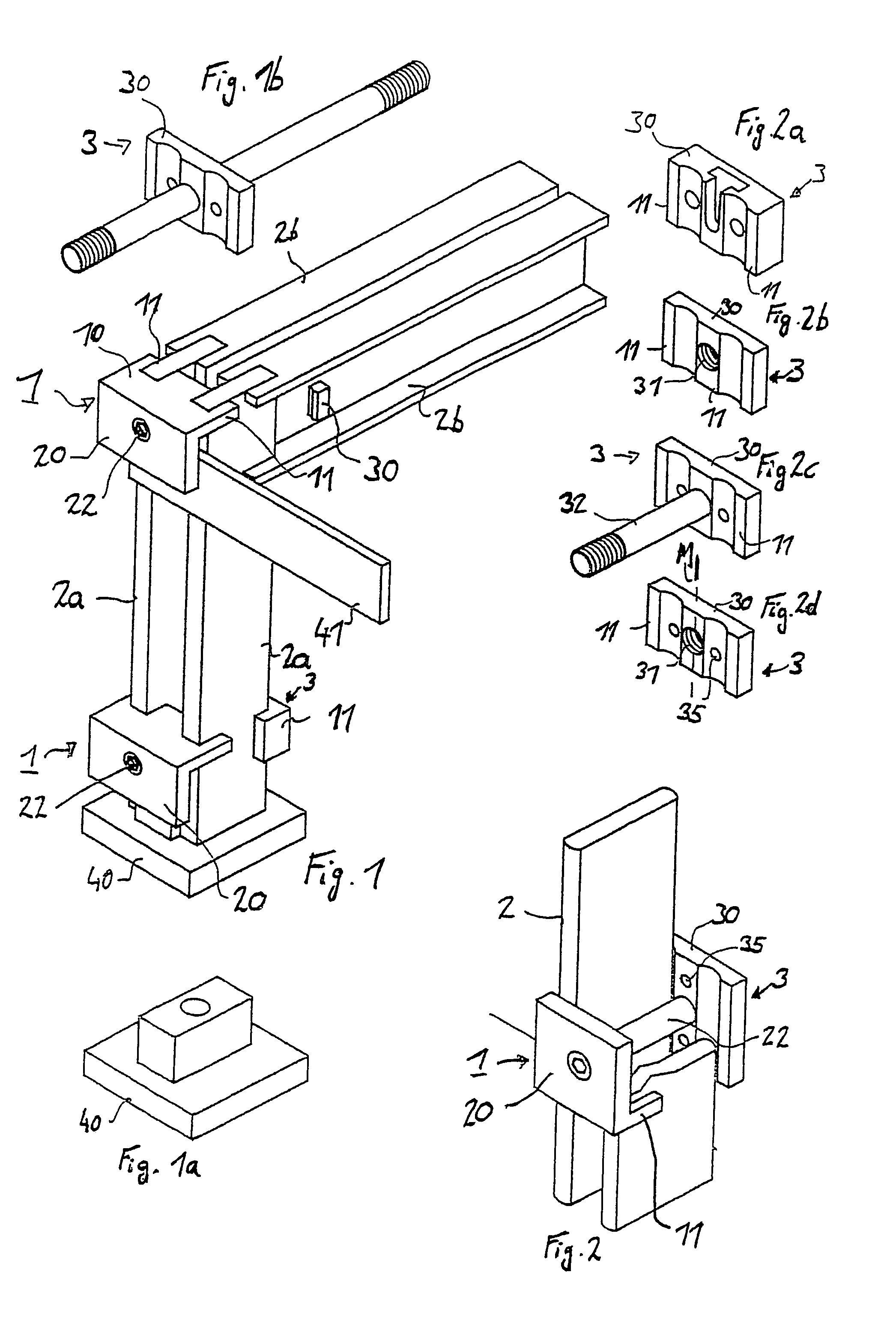
[0055]Arranged at the bottom end of the profile elements 2a is a foot 40, which is illustrated in detail in FIG. 1a. The two profile elements 2a are oriented parallel to one another and are partially enclosed on their narrow sides by the clamping element 1, more precisely by the protrusions 11 which project from a base part 10 arranged on the clamping plate 20. Arranged on the other side of the profile elements 2a is a locking element 3, of which the pro...


PUM


Abstract

System for connecting profile elements includes a separate clamping element having a clamping plate and at least one protrusion and a separate locking element having a base plate and at least one protrusion. In an assembled state, the locking element butts against that side of the profile elements located opposite the clamping element, such that protrusions of the locking element and of the clamping element are directed toward one another. A device is utilizes to clamp the clamping element and the locking element together such that, in the assembled state, the profile elements are clamped in between the clamping element and the locking element. The device being guided centrally between the profile elements.

Description

BACKGROUND OF THE INVENTION[0001]1. Field of the Invention[0002]The invention relates to a system, a clamping element and a locking element for connecting profile elements. The system and the clamping or locking elements are suitable, in particular, for the universal fastening of structural parts, in particular of profiles and panels on profile elements and / or for connecting profile elements to one another, to fixed objects or to add-on parts.[0003]2. Background Description[0004]In order to erect racks, wall claddings, storage means, fair stands or the like which can be adjusted in a variety of ways, can be subjected to high loading and can be assembled and dismantled as desired, use has usually been made up until now of profiles which have periodically repeating recesses such as holes or notches. The smaller the spacings between these recesses, the more precisely can the elements fitted on the profiles be adjusted. Racks of small to medium size usually have four profiles which are ...

Claims


Application Information

Patent Timeline
IPC IPC(8): F16B7/04F16B5/06A47B57/54F16B2/06F16B2/20F16B7/18
CPCA47B57/54F16B2/065F16B7/18Y10T403/7129Y10T403/7171Y10T403/4674Y10T403/7188Y10T403/7141F16B2200/40A47B47/00
Inventor BASLER, NORBERT
Owner BASLER NORBERT
Why Eureka
Try Eureka