Method and device for oxygen production by low-temperature separation of air at variable energy consumption

Active Publication Date: 2017-10-24
LINDE AG
View PDF5 Cites 0 Cited by
  • Summary
  • Abstract
  • Description
  • Claims
  • Application Information

AI Technical Summary

Benefits of technology

The invention allows for efficient use of the separative work in liquid oxygen by adjusting the amount of nitrogen compressed in the cold compressor. This results in a reduction in power required for the additional condenser and a reduction in outlay associated with liquefaction. The use of a booster air compressor also results in energy savings.

Problems solved by technology

A “side condenser” is to be understood as being a condenser-evaporator which is designed almost exclusively for the indirect transfer of latent heat from a condensing process stream evaporation to an evaporating process stream against a second, condensing process stream and is not or substantially not suitable for the transfer of sensible heat.
However, that process is carried out not with a constant throughput through the distillation column system with a varying product amount, but with varying operation in dependence on varying energy costs.

Method used


Image

  • Method and device for oxygen production by low-temperature separation of air at variable energy consumption
  • Method and device for oxygen production by low-temperature separation of air at variable energy consumption
  • Method and device for oxygen production by low-temperature separation of air at variable energy consumption

Examples


Embodiment Construction

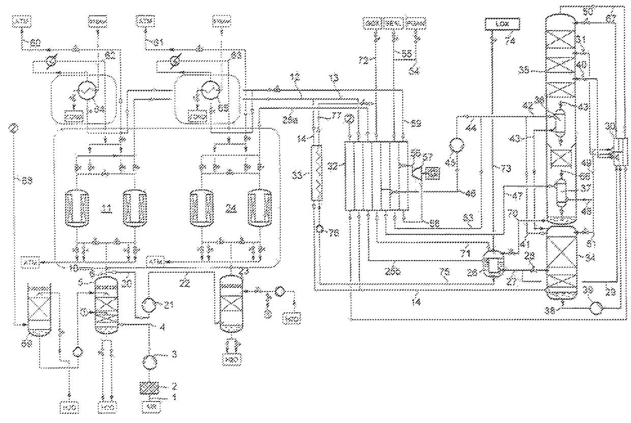
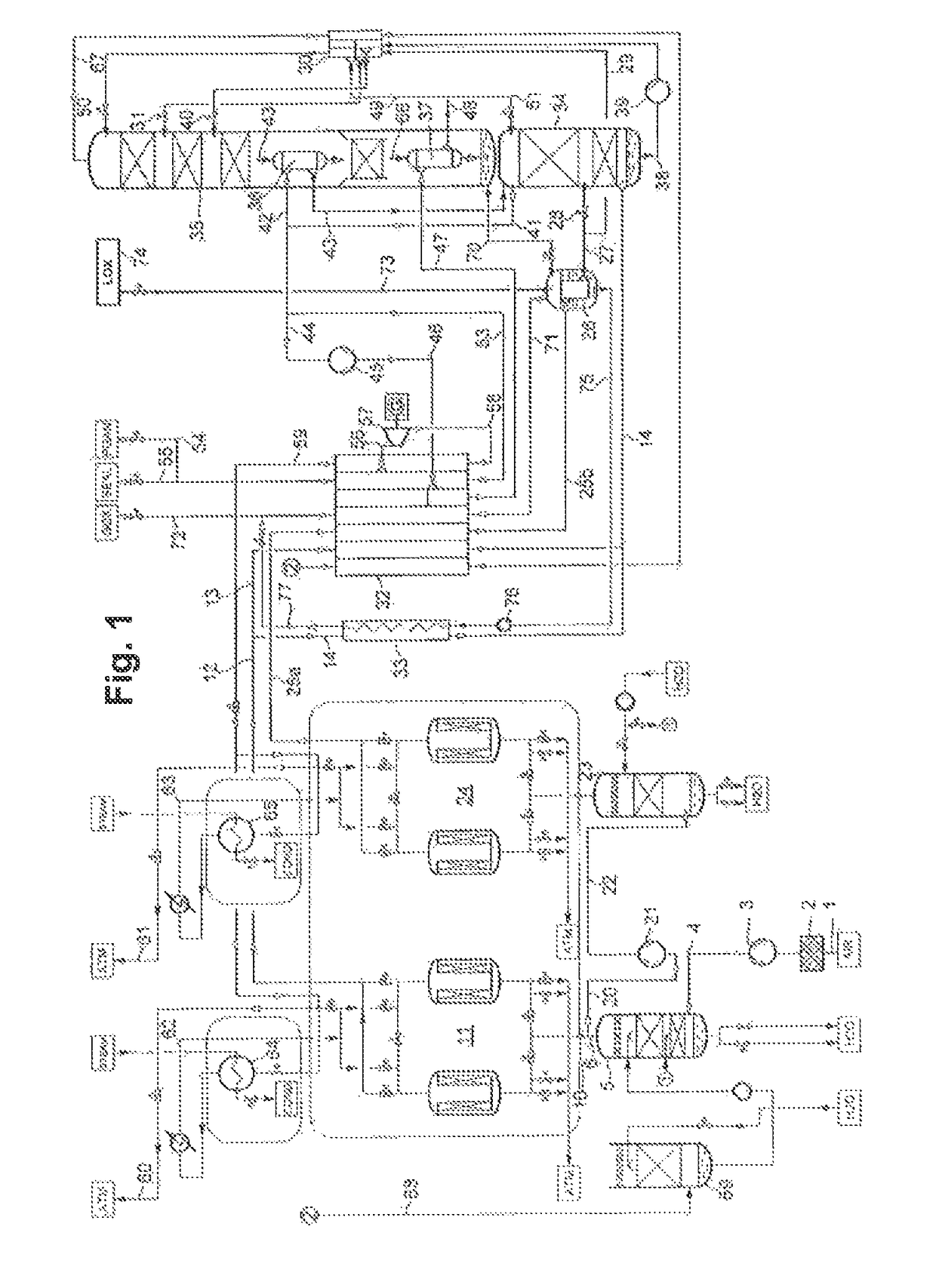
[0111]The method of FIG. 1 is first described below with reference to the first operating mode (here: normal operation when the energy price is relatively low). Atmospheric air 1 (AIR) is drawn via a filter 2 from a main air compressor (MAC) 3 and compressed to a pressure of 3.6 bar, for example. The total air stream 4 compressed in the main air compressor is precooled in a first direct contact cooler 5 by means of direct countercurrent with water. Downstream of the first direct contact cooler 5, the total air stream 6 is branched into a first partial air stream 10 and a second partial air stream 20.

[0112]The first partial air stream 10 is purified in a first purifying unit 11 and fed via line 12, at the outlet pressure of the main air compressor minus line losses, to the hot end of a main heat exchanger. The main heat exchanger is formed in the example by two sections 32, 33 which are connected in parallel on the air side and are preferably both formed by plate heat exchanger block...


PUM


Abstract

A method and device to produce oxygen by the low-temperature separation of air at variable energy consumption. A distillation column system comprises a high-pressure column, a low-pressure column and a main condenser, a secondary condenser and a supplementary condenser. Gaseous nitrogen from the high-pressure column is liquefied in the main condenser in indirect heat exchange with an intermediate liquid from the low-pressure column. A first liquid oxygen stream from the bottom of the low-pressure column is evaporated in the secondary condenser in indirect heat exchange with feed air to obtain a gaseous oxygen product. The supplementary condenser serves as a bottom heating device for the low-pressure column and is heated by means of a first nitrogen stream from the distillation column system, which nitrogen stream was compressed previously in a cold compressor.

Description

CROSS-REFERENCE TO RELATED APPLICATIONS[0001]This application claims priority under 35 USC §119 to International Patent Application No. PCT / EP2014 / 001892, filed on Jul. 10, 2014, which claims priority from European Patent Application EP 13 003 510.8 filed on Jul. 11, 2013.BACKGROUND OF THE INVENTION[0002]The invention relates to a method for oxygen production by low-temperature separation of air with variable energy consumption in a distillation column system having a high-pressure column, a low-pressure column as well as a main condenser and a side condenser which are both in the form of condenser-evaporators, wherein in the method[0003]atmospheric air is compressed to a total air pressure in a main air compressor, cooled in a main heat exchanger and fed at least in part to the high-pressure column,[0004]in the main condenser, gaseous nitrogen from the high-pressure column is at least partially liquefied,[0005]at least a portion of the liquid nitrogen generated in the main condense...

Claims


Application Information

Patent Timeline
IPC IPC(8): F25J3/00F25J3/04F25J3/06
CPCF25J3/04836F25J3/0409F25J3/04018F25J3/04024F25J3/0426F25J3/0483F25J3/0486F25J3/04157F25J3/04169F25J3/04181F25J3/04206F25J3/04218F25J3/04309F25J3/04351F25J3/04412F25J3/04418F25J3/04424F25J3/04496F25J3/04581F25J3/04618F25J3/04812F25J3/04878F25J3/04884F25J3/04957F25J3/0605F25J3/066F25J3/0406F25J2250/50F25J2200/06F25J2200/54F25J2205/32F25J2205/34F25J2205/62F25J2205/70F25J2210/50F25J2230/04F25J2230/24F25J2230/30F25J2230/42F25J2235/52F25J2240/70F25J2250/04F25J2250/40F25J3/04054
Inventor KIRCHNER, LARSGOLOUBEV, DIMITRI
Owner LINDE AG
Why Eureka
Try Eureka