
Ball exerciser

Active Publication Date: 2008-02-05
WANG WEN CHING
View PDF13 Cites 22 Cited by
  • Summary
  • Abstract
  • Description
  • Claims
  • Application Information

AI Technical Summary

Benefits of technology

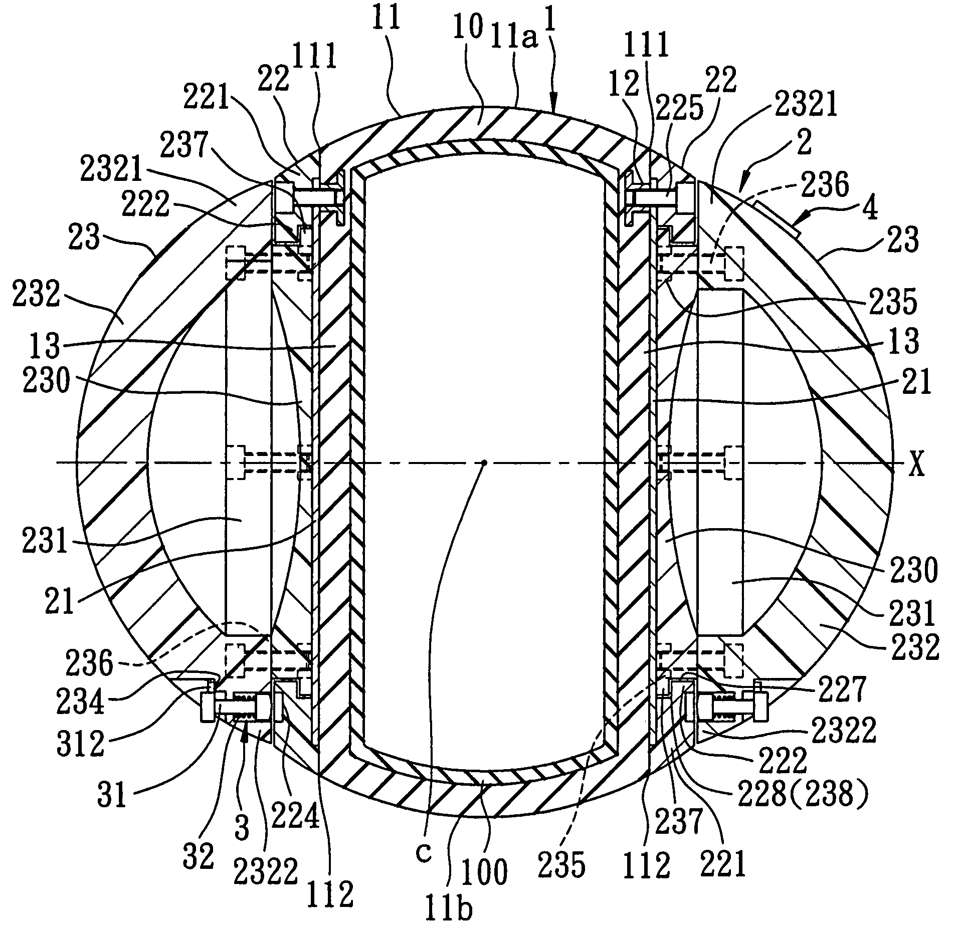
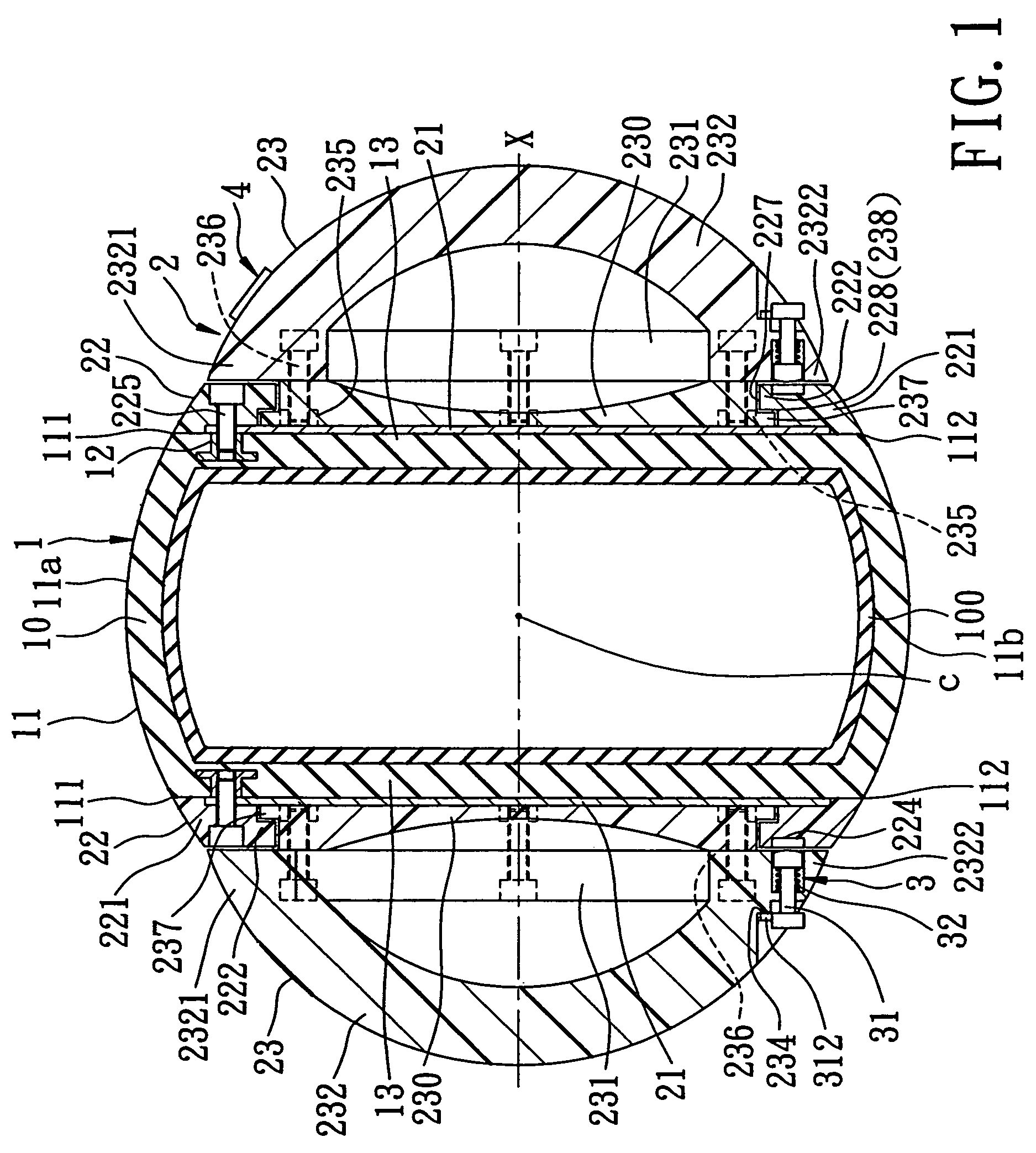
[0006]The object of the present invention is to provide a ball exerciser which can meet different exercise requirements of a user and which can roll smoothly when gripped by the user.

Problems solved by technology

However, the conventional ball exerciser is disadvantageous in that the roughened outer surface or finger holes are inconvenient to grasp by the user when used for rolling.
However, since the grip members are fixed to the ball body, rolling of the ball body is obstructed when the user grips the grip members, thereby limiting the kinds of exercise modes that can be performed with the exercise apparatus.

Method used


Image

  • Ball exerciser
  • Ball exerciser
  • Ball exerciser

Examples


first embodiment

[0026]Referring to FIG. 4, the second preferred embodiment of a ball exerciser according to this invention is shown to be similar to the first embodiment in construction and function, except that the rolling body 1 has an integrally formed structure, and the first and second stationary coupling members 22 are mounted on the first and second lateral mount walls 13, respectively, without the reinforcement plates interposed therebetween.

third embodiment

[0027]Referring to FIG. 5, the third preferred embodiment of a ball exerciser according to this invention is shown to be similar to the previous embodiments in construction and function. In the third embodiment, each of the first and second lateral mount walls 13 is concaved toward the center point (C) so as to form an outwardly facing concave surface 131. Each of the first and second stationary coupling members 22 is configured to extend along and be compliant with the outwardly facing concave surface 131 so as to form a first (second) concave major wall. The first (second) concave major wall has a first (second) convex major surface 2211 which is compliantly engaged with the respective outwardly facing concave surface 131, and a first (second) concave major surface 2212 which is opposite to the first (second) convex major surface 2211 to serve as the first (second) stationary coupling end. Each of the first and second movable coupling members 230 is configured to extend from the r...

fourth embodiment

[0029]Referring to FIG. 6, the fourth preferred embodiment of a ball exerciser according to this invention is shown to be similar to the previous embodiments in construction and function. In the fourth embodiment, each of the first and second lateral mount walls 13 has an outwardly facing straight surface which extends in the transverse direction. Each of the first and second stationary coupling members 22 has a straight major wall which is configured to extend along and be compliant with the outwardly facing straight surface, and a coupling shaft 229 which extends from the straight major wall along the rolling axis (X) to serve as the first (second) stationary coupling end. Each of the first and second movable coupling members 230 has a straight major surface which is disposed to confront the straight major wall, and an inner peripheral wall which extends to surround the respective coupling shaft 229 so as to serve as the first (second) movable coupling end, and which is journalled...


PUM


Abstract

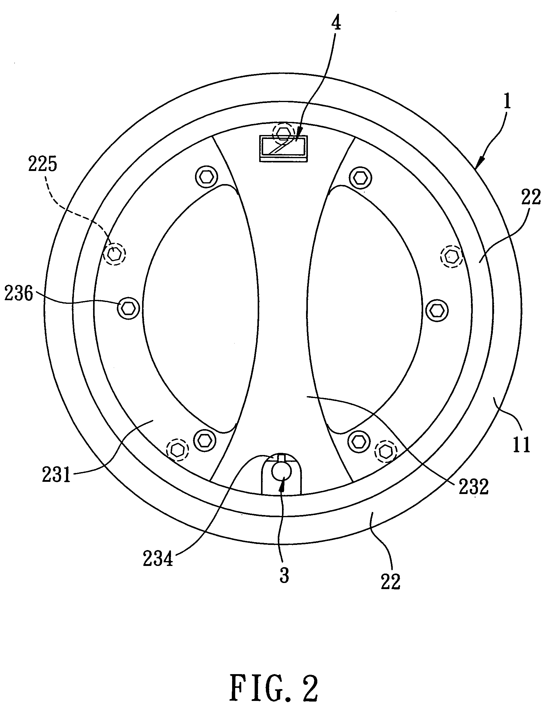
A ball exerciser includes a deformable rolling body having an outer surrounding wall surface and at least one lateral mount wall, a rigid stationary coupling member secured to the lateral mount wall and having a stationary coupling end distal from the lateral mount wall, a movable coupling member having a movable coupling end disposed to be swivelable and frictionally rotatable relative to the stationary coupling end about a rolling axis, a grip including a grip segment which is spaced apart from the lateral mount wall and which is coupled to the movable coupling end so as to permit the grip segment to swivel with the movable coupling member.

Description

BACKGROUND OF THE INVENTION[0001]1. Field of the Invention[0002]This invention relates to a ball exerciser, more particularly to a ball exerciser which can be used to perform various exercises.[0003]2. Description of the Related Art[0004]A conventional ball exerciser has a roughened outer surface or finger holes to permit holding by the user when it is used to do various exercises, such as swinging, lifting and rolling of the ball. However, the conventional ball exerciser is disadvantageous in that the roughened outer surface or finger holes are inconvenient to grasp by the user when used for rolling.[0005]In U.S. Pat. No. 6,964,635 B2, the applicant disclosed an exercise apparatus that includes a ball body and two grip members disposed securely and respectively on two opposite sides of the ball body to facilitate grasping of the ball body by the user so that he / she can perform different exercises. However, since the grip members are fixed to the ball body, rolling of the ball body ...

Claims


Application Information

Patent Timeline
IPC IPC(8): A63B21/00A63B43/02A61H15/00
CPCA63B21/06A63B22/20A63B41/00A63B43/02A63B23/1236A63B2071/0625A63B2220/17A63B2230/75A63B41/125
Inventor WANG, WEN-CHING
Owner WANG WEN CHING
Learn More