Roller chain and guide unit having the same therein

a technology of guide unit and roller chain, which is applied in the direction of bearings, shafts and bearings, bearings, etc., can solve the problems of difficult to ensure the provision of space enough to reserve lubricant therein, the roller might be likely to experience any skew movement, and the roller is difficult to control the posture of the roller, so as to achieve high operational speed, mechanical strength and accuracy

Active Publication Date: 2005-07-14
NIPPON THOMPSON
View PDF0 Cites 13 Cited by
  • Summary
  • Abstract
  • Description
  • Claims
  • Application Information

AI Technical Summary

Benefits of technology

[0010] The present invention, therefore, has as its primary object to overcome the major problems discussed earlier of the prior roller chain, and in particular to provide a roller chain in which more than one rolling element of cylindrical roller is guided certainly on axially opposite circular ends thereof to be kept against moving on the skew even under carrying high loads while a carrier belt is made to have a large space to reserve lubricant therein, whereby the carrier belt helps ensure that the roller runs steadily while following a circuit made ...

Problems solved by technology

Meanwhile, the prior linear motion guide unit using rolling elements of cylindrical roller enables to carry larger load compared with the linear motion guide unit of another type having balls, but vulnerable to an adverse happening where the rolling axis of the roller would be tilted when the load varies, that is to say, the roller might be likely to experience any skew movement.
Moreover, the conventional linear motion guide units of the sort as stated earlier, as undergoing a large thrust load in the axial direction thereof after the roller has moves on the skew, is much tough in posture control of the roller.
With the roller chain constructed as recited earlier, any interval between any leading and trailing rollers is made up for the associated separator and, therefore, it is tough to make certain of the provision of space enough to reserve lubricant therein.
This co...

Method used


Image

  • Roller chain and guide unit having the same therein
  • Roller chain and guide unit having the same therein
  • Roller chain and guide unit having the same therein

Examples


Embodiment Construction

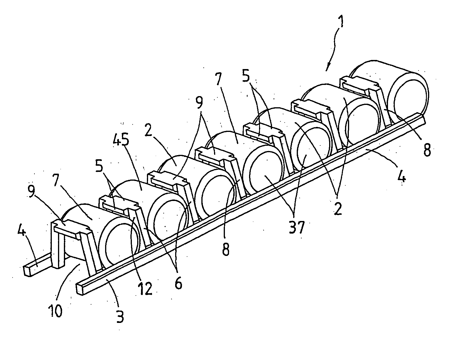
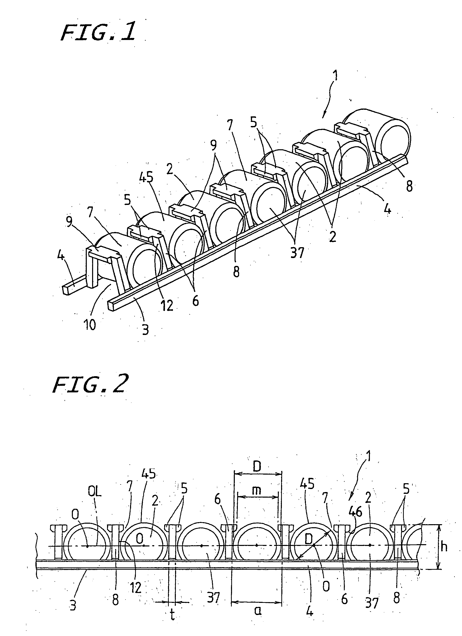
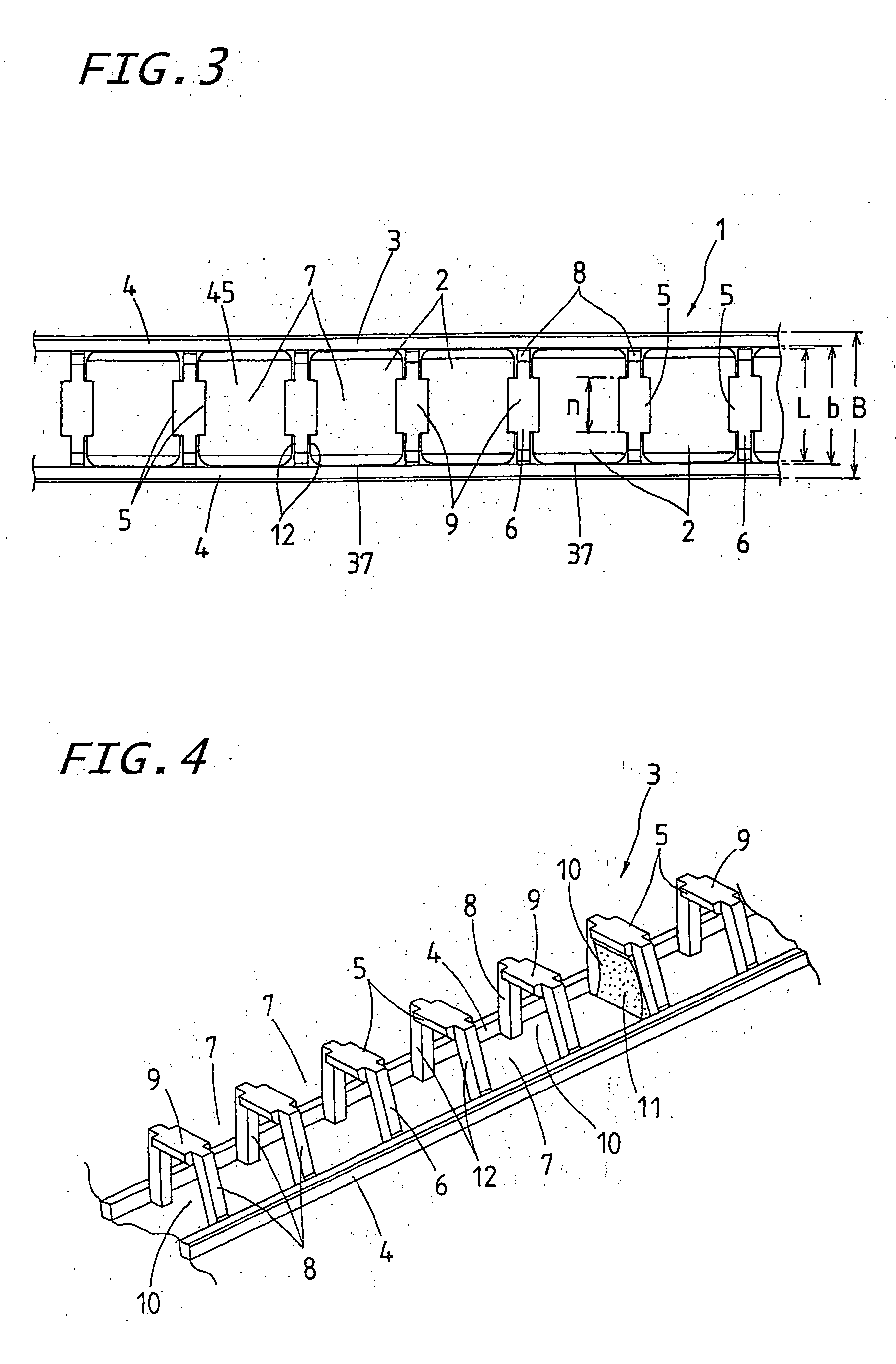
[0040] A roller chain according to the present invention will be readily appreciated by reference to the following detailed description when considered in connection with the accompanying drawings.

[0041] The roller chain of the present invention is expected for the application in a diversity of guide units including a linear motion guide unit, curvilinear motion guide unit, finite linear motion unit, and so forth. Moreover, a guide unit of the present invention having installed the roller chain 1 therein is adapted for extensive use between two machine members that move or travel relative to one another in diverse machines including, for example semiconductor manufacturing machines, machine tools, industrial robots, precision assembly machines, and so forth, which require high stiffness, high-speed sliding performance, high-acceleration sliding performance, and so on.

[0042] Constructional features of the present invention reside in a guide unit mainly comprised of an elongated gui...


PUM


Abstract

A roller chain is provided, which is composed of more than one roller and a carrier belt. The roller chain helps make sure of keeping the rollers against moving on the skew even under carrying high loads while the carrier belt is made to have a large space to reserve lubricant sufficient to ensure good lubrication. The carrier belt is comprised of a pair of continuous bands lying to carry or bear axially opposite ends of the roller across an area set off-centre from an axis of the roller, and more than one U-type separator to join the continuous bands together with one another. The U-type separators 6 are each composed of a pair of legs joined together with their associated continuous bands, and a horizontal bridge interconnecting the sidewise spaced leg with each other.

Description

FIELD OF THE INVENTION [0001] The present invention relates to a chain of rollers, hereinafter called “roller chain”, comprised of more than one rolling element of cylindrical roller and a carrier belt to keep the rolling element therein, and also relates to a guide unit comprised of a guide rail, a slider that fits over the guide rail for movement relative to the guide rail by virtue of the rolling elements, and the roller chain installed to roll through a recirculation circuit made between the slider and the guide rail. BACKGROUND OF THE INVENTION [0002] The recently remarkable advance in robotization technology in many industrial machines extensively requires any guide unit that is high in sliding performance as well as operational speed. To cope with the requirements stated earlier, the roller chain has been developed in which more than one rolling element of cylindrical roller is held in the retainer to keep any adjacent rolling elements from coming into direct engagement with ...

Claims


Application Information

Patent Timeline
IPC IPC(8): F16C29/06F16C33/46F16C33/49F16C33/66
CPCF16C33/506F16C29/065
Inventor NAGAO, SHOUJIIZUMI, HIROAKIKATAOKA, NORIAKI
Owner NIPPON THOMPSON
Why Eureka
Try Eureka