Portable tire and wheel lifting apparatus

a technology for lifting equipment and tires, applied in the field of tools, can solve the problems of increasing the number of people experiencing tire problems on the road, affecting the mobility of people, and affecting the mobility of people, and achieve the effect of reducing the cargo area

Active Publication Date: 2008-02-26
MITCHELL KNECOLE A +1
View PDF38 Cites 13 Cited by
  • Summary
  • Abstract
  • Description
  • Claims
  • Application Information

AI Technical Summary

Benefits of technology

[0007]A portable tire and wheel lifting apparatus for use in changing an automobile tire according to the present invention includes a base, a pair of lifting arms pivotally coupled in a scissor configuration, pneumatic cylinders, an air input device, and an air outlet valve. When in use, the portable tire and wheel lifting apparatus is initially in a retracted configuration and placed on the ground near a vehicle's hub. A tire and wheel are then smoothly rolled from the ground to the lifting arms. The air input device adds air to the pneumatic cylinders, causing the lifting arms to move from the retracted configuration to an extended configuration, thus raising the tire and wheel to the desired height. The tire and wheel can then be turned until the holes of the rim line up with the vehicle's hub, allowing the tire and wheel to be fastened to the vehicle. After the tire and wheel are fastened to the vehicle, the air outlet valve may be actuated to selectively release air from the pneumatic cylinders, allowing the lifting arms to move from the extended configuration to the retracted configuration. The lifting arms may include support members or rollers to aid in supporting and rotating the tire and wheel. Further, the tire and wheel lifting apparatus is small enough to fit inside the cavern defined by a tire and wheel, allowing it to be stored in the automobile's spare tire and thus take up minimal cargo area.
[0008]Therefore, a general object of this invention is to provide a portable tire and wheel lifting apparatus that is compact and lightweight.
[0009]Another object of this invention is to provide a portable tire and wheel lifting apparatus, as aforesaid, that can be conveniently stored in smaller vehicles.
[0010]Still another object of this invention is to provide a portable tire and wheel lifting apparatus, as aforesaid, that does not require arm strength to power the lifting means.
[0011]Yet another object of this invention is to provide a portable tire and wheel lifting apparatus, as aforesaid, that does not require the user to maintain his weight on the device.

Problems solved by technology

Longer and longer average commuting distances mean more people will experience tire problems on the road.
Although some can afford roadside service, for others this is beyond their means or simply unavailable.
This weight presents a problem for smaller individuals, the elderly, and others.
A jack is commonly used to lift a car, but no comparable product exists to aid motorists in lifting the tire and placing it onto the car.
Devices for lifting vehicle wheels are known in the art, such as in U.S. Pat. No. 4,050,597, U.S. Pat. No. 4,771,531, U.S. Pat. No. 5,007,789, U.S. Pat. No. 5,505,578, U.S. Pat. No. 6,095,745, and U.S. Pat. No. 6,382,644, but are directed to lifting large vehicle wheels, are neither compact nor lightweight, cannot be conveniently stored in smaller vehicles, and thus do not aid motorists in changing a tire on a roadside.
Further, many of these devices require arm strength to power the lifting means.
This required arm strength is often problematic for smaller individuals, the elderly, and others.
Since the rotational force gained from levers is in direct proportion to the distance between the fulcrum and the applied force, these devices are often too large to be conveniently stored in an automobile.
Moreover, these devices are often difficult, cumbersome, or messy to use since an individual must keep his weight on the lever at all times while changing the tire.

Method used


Image

  • Portable tire and wheel lifting apparatus
  • Portable tire and wheel lifting apparatus
  • Portable tire and wheel lifting apparatus

Examples


Embodiment Construction

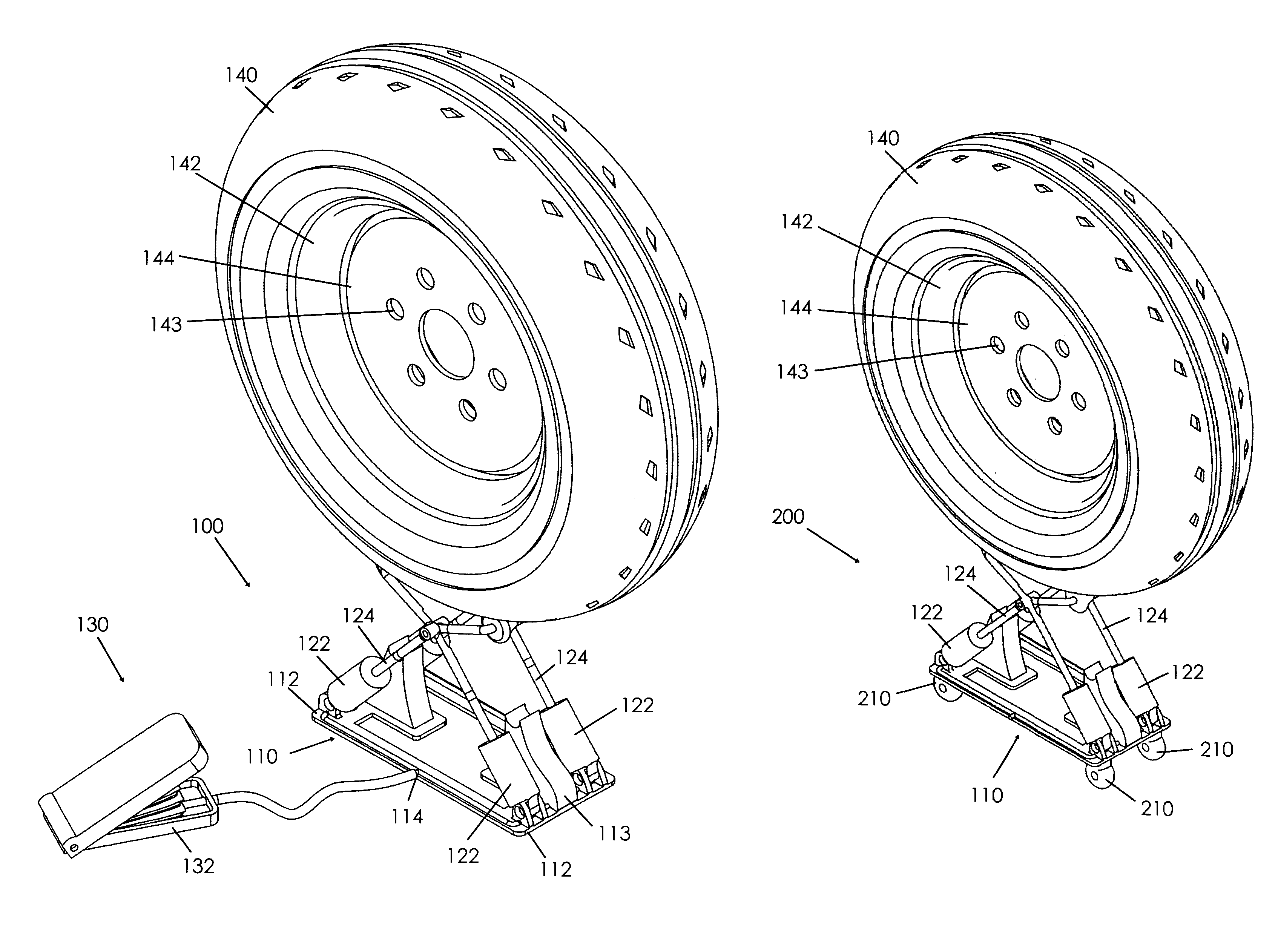
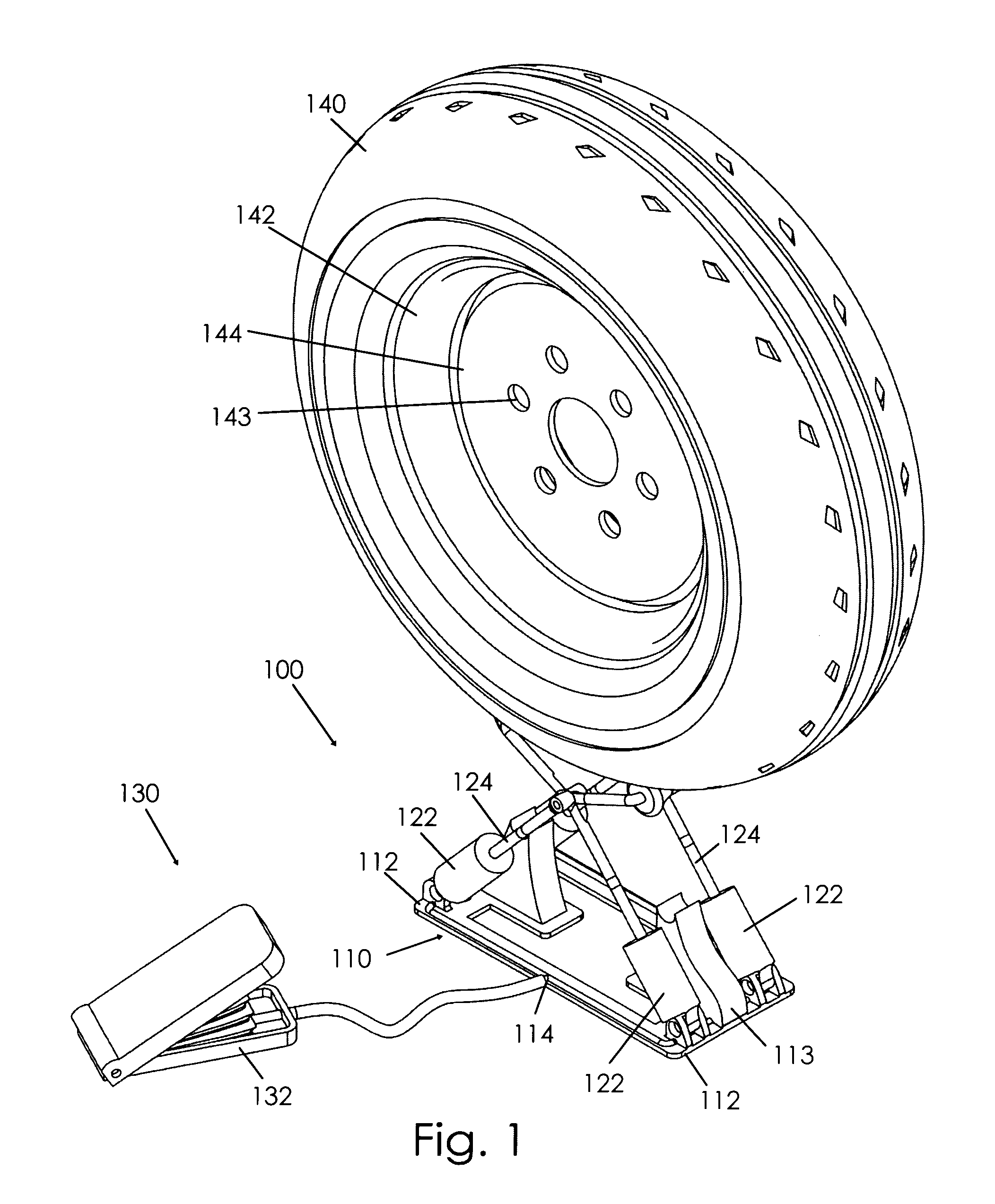
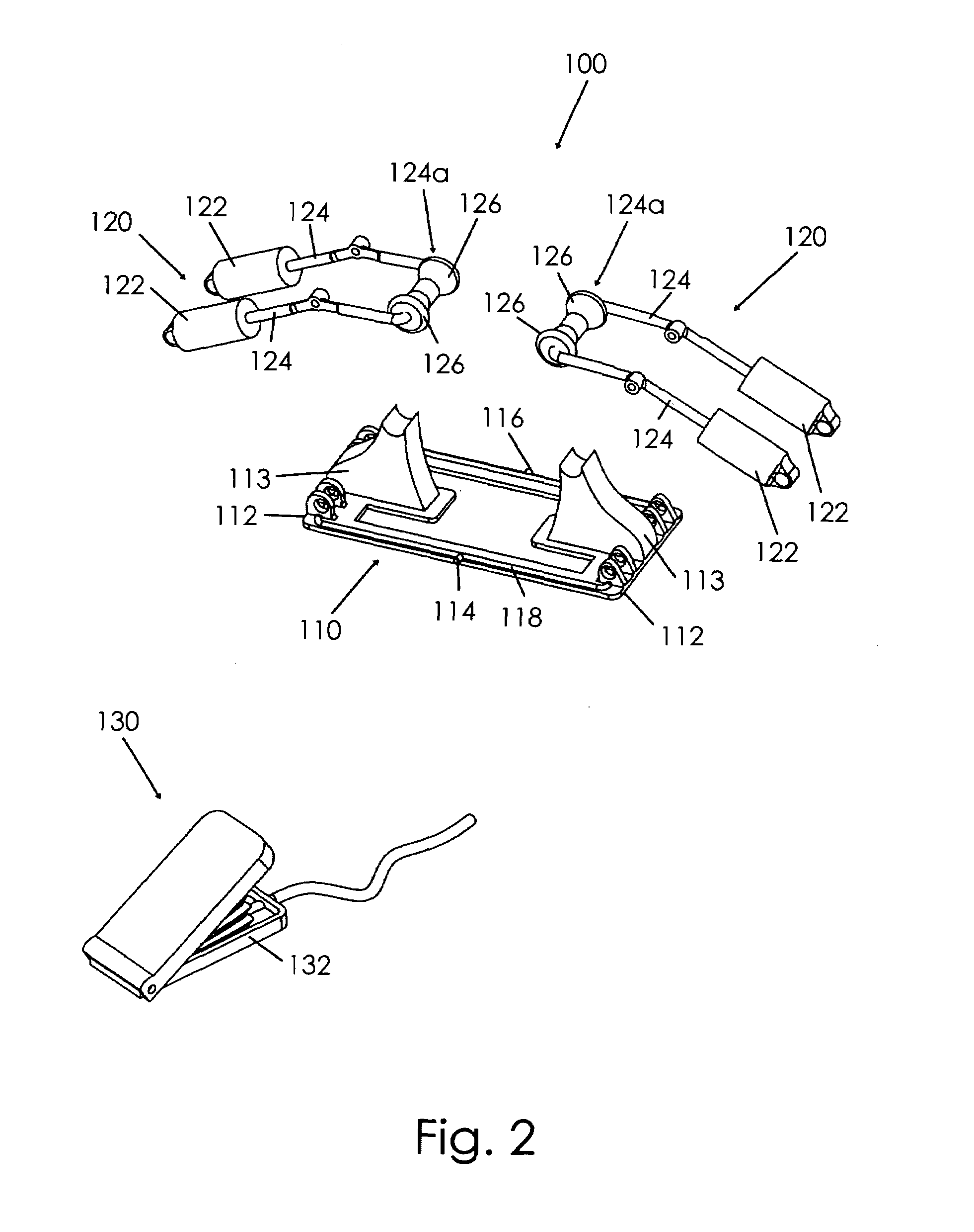
[0020]A portable tire and wheel lifting apparatus according to the present invention will now be described with reference to FIGS. 1 through 4 of the accompanying drawings. More particularly, a portable tire and wheel lifting apparatus 100 according to a now preferred embodiment includes a base 110 with opposed sides 112 and a pair of piston cylinder combinations 120. Each piston cylinder combination 120 has at least one pneumatic cylinder 122 and a lifting arm 124. The pneumatic cylinders 122 of the respective piston cylinder combinations 120 are pivotally coupled to the respective opposed sides 112 of the base 110. First / lower ends of the lifting arms 124 are received by respective cylinders 122 and extend therefrom and are pivotally coupled to one another, creating a scissor configuration that allows for relative up and down movement (FIGS. 3a and 3b). It is understood that each combination 120 may include a pair of cooperating cylinders 122 and arms 124 (FIG. 2). The top ends 12...


PUM


Abstract

A portable tire and wheel lifting apparatus includes a base, a pair of lifting arms pivotally coupled in a scissor configuration, pneumatic cylinders, an air input device, and an air outlet valve. In use, a tire and wheel are smoothly rolled from the ground to the lifting arms, which are in a retracted configuration. The air input device adds air to the pneumatic cylinders, causing the lifting arms to move from the retracted to an extended configuration, thus raising the tire and wheel. The tire and wheel are turned to line up the rim with the vehicle's hub and fastened to the vehicle. The air outlet valve selectively releases air from the pneumatic cylinders, allowing the lifting arms to move from the extended to the retracted configuration. The tire and wheel lifting apparatus is small enough to fit inside the cavern defined by a spare tire and wheel for storage.

Description

BACKGROUND OF THE INVENTION[0001]This invention relates generally to tools that aid in mounting wheels and tires upon vehicles and, more particularly, to a portable tire and wheel lifting apparatus that assists in the lifting and placing of a tire and wheel combination onto an automobile.[0002]Longer and longer average commuting distances mean more people will experience tire problems on the road. Although some can afford roadside service, for others this is beyond their means or simply unavailable. Further, some drivers take comfort in the knowledge that they can handle common maintenance tasks themselves.[0003]A full size, inflated car tire can weigh over 30 pounds, and truck tires can weigh even more. This weight presents a problem for smaller individuals, the elderly, and others. A jack is commonly used to lift a car, but no comparable product exists to aid motorists in lifting the tire and placing it onto the car.[0004]Devices for lifting vehicle wheels are known in the art, su...

Claims


Application Information

Patent Timeline
Patent Type & Authority Patents(United States)
IPC IPC(8): B62B3/02B62B1/00
CPCB60B29/001B60B29/002B66F3/245B60B2340/12B60B2340/34B60B2340/36B60B2900/3313B60Y2200/11B62B5/0083B62B2202/031B62B2203/10
Inventor MITCHELL, KNECOLE A.RUSSELL, III, TYLER
Owner MITCHELL KNECOLE A
Why Eureka
Try Eureka