
Linear motion guide unit with roller

Active Publication Date: 2009-01-15
NIPPON THOMPSON
View PDF8 Cites 14 Cited by
  • Summary
  • Abstract
  • Description
  • Claims
  • Application Information

AI Technical Summary

Benefits of technology

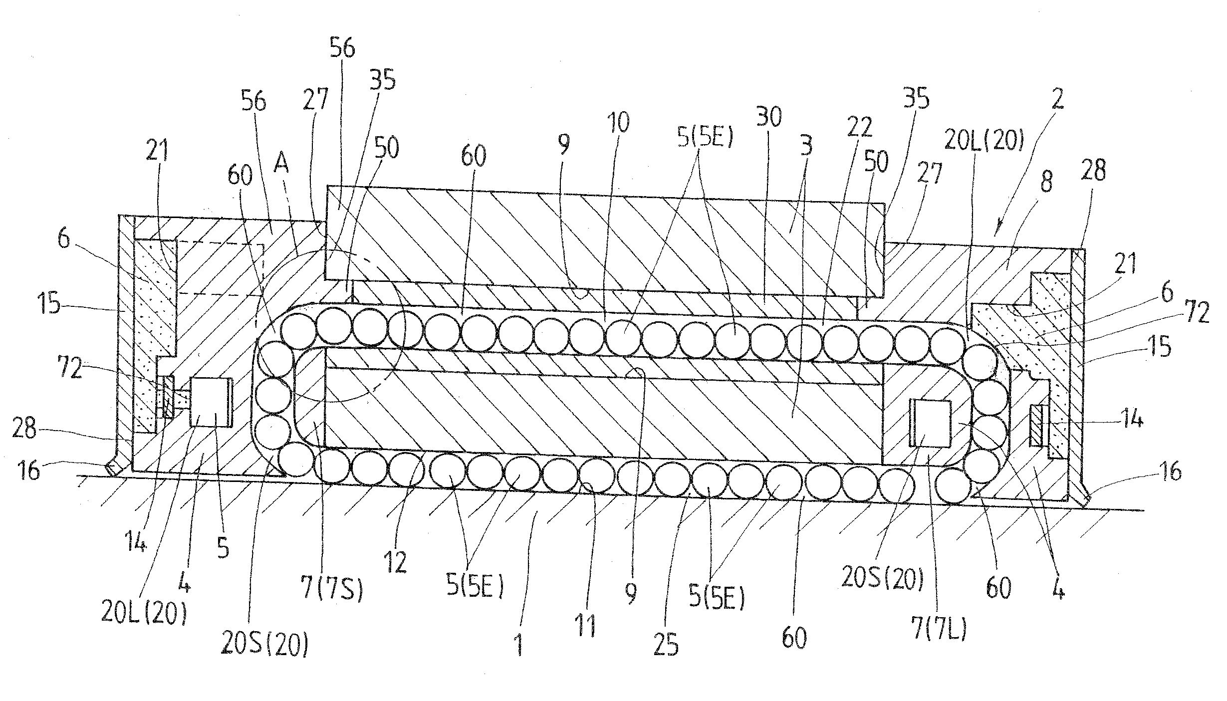
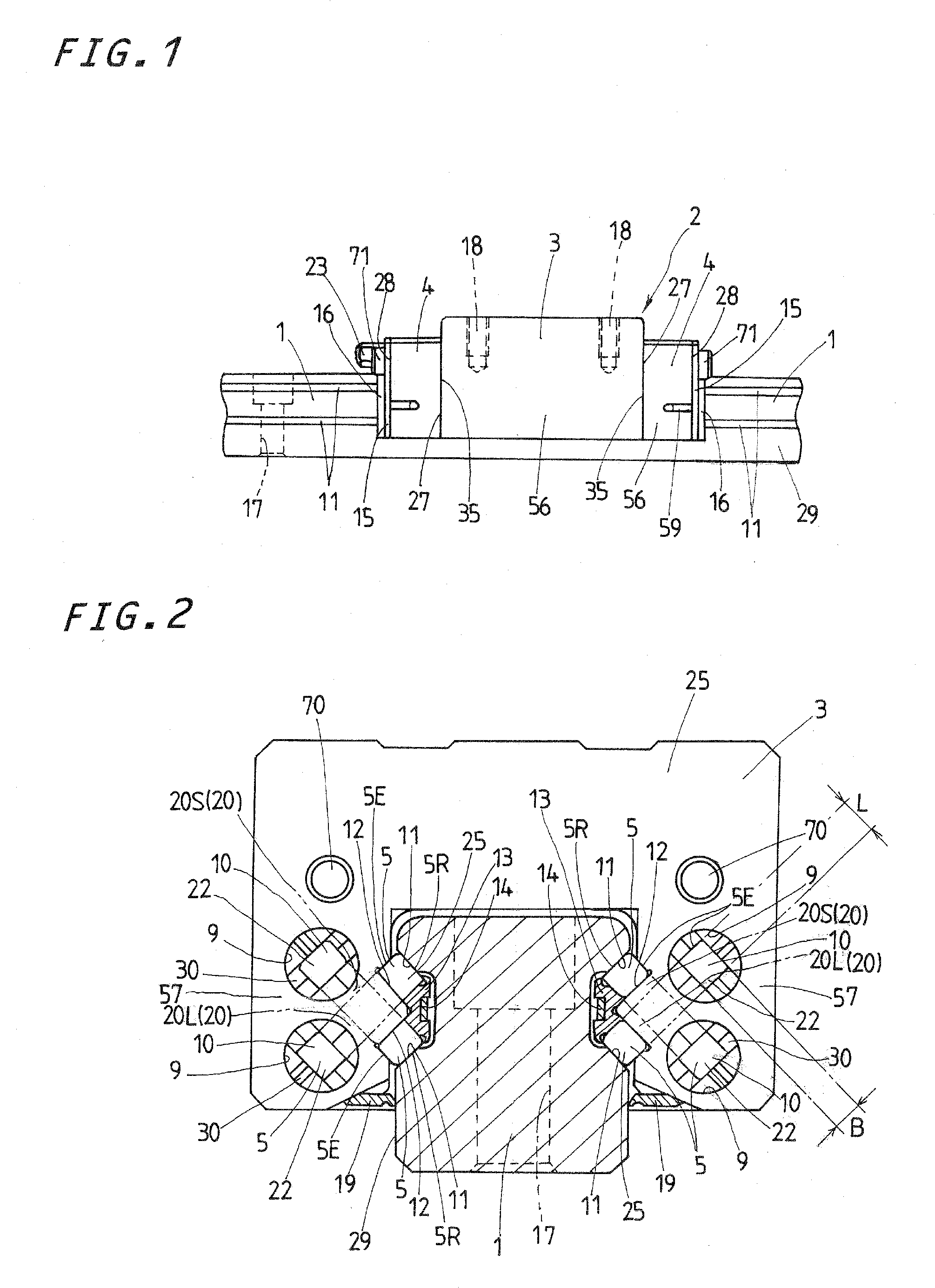
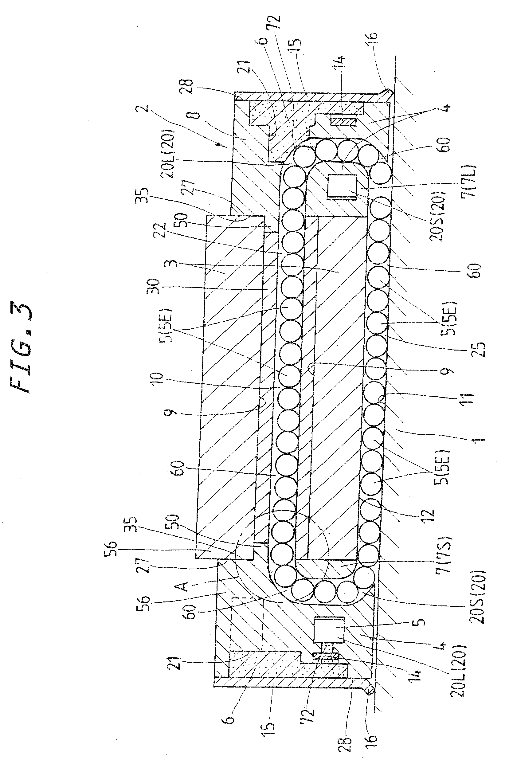
[0009]The present invention has for its primary object to overcome the major challenge as stated earlier in the prior linear motion guide units, and to provide a linear motion guide unit in which more than one roller serving as rolling elements is allowed to roll smoothly across joints between turnaround passages and the associated return passages. More particularly, the present invention provides a linear motion guide unit in which protrusions extending stepwise from an end of the turnaround passage come into complementary fit joints with an associated end of a tubular member defining the return passage to make wall surfaces to guide axially opposite ends of the roller, and the protrusions to guide the axially opposite ends of the roller are bisected into two halves which are different from each other in length spaced away from the end surface of the end cap to make the complementary fit joints witch a tubular member to define the return passage therein at different locations along the rolling direction of the roller, whereby the complementary fit joints on the wall surfaces to guide the axially opposite ends of the roller are separated and staggered from each other at a mating surface bisecting a width of the wall surface and extending in parallel with rolling direction of the roller to make contact with the axially opposite ends of the roller at different locations, helping the roller get over the joints smoothly.
[0019]With the linear motion guide unit constructed as stated earlier, the rollers even though small in diameter are allowed to get over the joint between the turnaround passage and the associated return passage without getting stumbled or caught on any gap at the joint. Thus, the linear motion guide unit of the present invention can be expected to display the performances of high rigidity and accuracy even under severe operating requirements including high velocity and high acceleration / deceleration, thereby befitting for the relatively sliding parts in machinery including semiconductor fabricating equipment and measuring instruments.

Problems solved by technology

Some turning of the sleeve can lead to no practical problem when the balls are selected as the rolling elements.
With the sleeve rectangular in transverse section to allow the rollers running through there, in contrast, any turning or angular displacement of the sleeve, albeit slightly, causes any staggered relation in rectangular return passage between the sleeve and the associated end cap, getting the circulating motion of the rollers interfered.
Thus, even if there is any gap between the sleeve and the associated spigot, the rollers are apt to stumble on the gap when rolling across the connecting construction to lean or topple over to fall into the gap.
Thus, it still remains a significant challenge to ensure smooth, steady rolling motion o the rollers throughout the circulating circuit.

Method used


Image

  • Linear motion guide unit with roller
  • Linear motion guide unit with roller
  • Linear motion guide unit with roller

Examples


Embodiment Construction

[0035]The linear motion guide unit constructed according to the present invention is best adapted for use in any relatively sliding components in machinery as diverse as semiconductor fabricating equipment, precision machines, measurement / inspection instruments, machine tools, assembling machines, conveyers, various types of robots, medical instruments, micromachines, and so on. More particularly, the present invention is envisaged the provision of a butt joint with no gap in a circulating circuit to let a rolling element of small roller run smoothly across the butt joint throughout the circulating circuit. Referring now in detail to the drawings, the linear motion guide unit according to the present invention will be explained below.

[0036]The linear motion guide unit of the present invention is most favorable for the sort whose rolling elements are of rollers 5 small in diameter, and further makes certain of smooth rolling of rollers 5 throughout a circulating circuit 60 even under...


PUM


Abstract

A linear motion guide unit is envisaged smooth transfer of a roller from a turnaround passage to a return passage and vice versa across a joint between the turnaround passage and the associated return passage. Protrusions extending stepwise from an end of the turnaround passage come into complementary fit joints with an associated end of a tubular member defining the return passage to make wall surfaces to guide axially opposite ends of the roller, in which the joints are staggered or different in their locations between wall surfaces. The return passage is defined with a fore-and-aft hole of rectangular shape in transverse section inside a tubular member that fits into a bore made in the carriage. The tubular member is joined at lengthwise opposite ends thereof together to the protrusions that are raised above end surfaces of the end caps to extend the turnaround passage into the bore. Edges of the protrusions come into complementary fit joints with the associated ends of the tubular member to provide wall surfaces to guide axially opposite ends of the roller.

Description

FIELD OF THE INVENTION[0001]The present invention relates to a linear motion guide unit with small rollers comprised of, for example an elongated guide rail and a slider that fits over or conforms to the guide rail to move relative to the elongated guide rail by virtue of more than one small roller.BACKGROUND OF THE INVENTION[0002]Linear motion guide units are extensively used in recent years with installed in the relatively sliding parts in machinery including machine tools, assembling machines, conveyors, semiconductor fabricating equipment, measuring instruments, and so on, while finding further increased applications in various industrial fields. Moreover, the linear motion guide units of the class using more than one roller, although used in diverse industrial fields, are still needed to get more in stiffness and accuracy, shrunken in size, and more adaptable to severe operating conditions including high velocity and high acceleration / deceleration in sliding movement. The desig...

Claims


Application Information

Patent Timeline
IPC IPC(8): F16C29/06
CPCF16C29/0609F16C29/0611F16C29/065
Inventor KAKEI, SHIGEKI
Owner NIPPON THOMPSON
Learn More