Adjustable bridge for acoustic stringed instruments

a guitar and bridge technology, applied in the direction of instruments, motors/generators/converter stoppers, dynamo-electric converter control, etc., can solve the problems of instrument detune, instrument to be easily retrofitted, and rarely if ever achieve the precise degree of intonation. , to achieve the effect of conserving the sonority of the instrumen

Inactive Publication Date: 2008-02-05
HAGEN JOHN
View PDF37 Cites 20 Cited by
  • Summary
  • Abstract
  • Description
  • Claims
  • Application Information

AI Technical Summary

Benefits of technology

[0019]Another object is to preserve the sonority of the instrument by utilizing acoustically resonant materials to transmit string vibration to the sound board of the instrument.
[0020

Problems solved by technology

Conventional guitar construction utilizes a straight saddle positioned to produce correct intonation for the high and low E strings using what the manufacturer considers to be an “average string.” The remaining strings seldom if ever achieve the precise degree of intonation that produces optimal sound characteristics.
Thus, it becomes problematic whether even the high and low E strings will have good intonation.
Moreover, these musicians frequently travel to perform in different climatic zones which causes their instruments to de tune and require adjustment of the intonation.
Furthermore, airplane travel further exacerbates these problems because of the rapid changes in pressure and altitude.
Attempts have been made to produce a device to properly intonate acoustic guitars, none of which has proven to have any significant degree of commercial viability.
The type of construction described above is not adaptable to acoustic guitars because the transmission of string vibration is dampened resulting in diminished sustain (sound duration), sonority, and amplitude.
Moreover, the metal parts in electric guitar bridges used to support the string are not acoustically resonant producing an undesirable thin brittle tone.
The clearances between the parts not only allows movement of the parts in the intended manner for string length adjustment, but also an undesired movement imparted by the vibration of the string.
The undesirable vibration of the parts originating from string vibration uses sting energy, thereby, reducing the available energy for sound generation, resulting in a diminished sound amplitude pote

Method used


Image

  • Adjustable bridge for acoustic stringed instruments
  • Adjustable bridge for acoustic stringed instruments
  • Adjustable bridge for acoustic stringed instruments

Examples


embodiment

Preferred Embodiment

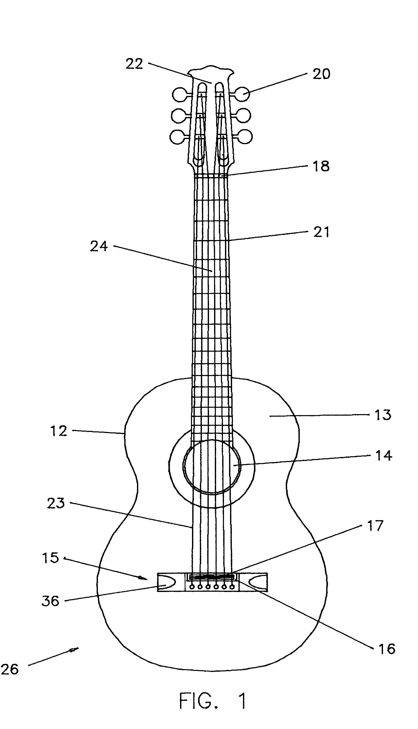
[0043]FIG. 1 shows the basic configuration of a conventional steel sing flat top acoustic guitar 25 having a guitar body 12 having a top or sound board 13 on which is mounted a bridge 15 below the sound hole 14. Guitar strings 23 anchored in the bridge 15 stretch over the saddles 17, the resonant cavity, and on to the head 22 and tuning machines 20. A bridge 15 and a saddle housing 16 containing moveable saddles 17 is mounted on the top 13 of the guitar body 12. Upraised metal ridges called frets 21 are located at designated intervals on the fret board 24 perpendicular to the strings. A typical guitar has about 20 frets. The theoretical placement of the frets are located conventionally, being sequentially derived from the logarithmic decrement of the 12th root of 2 for the desired scale length.

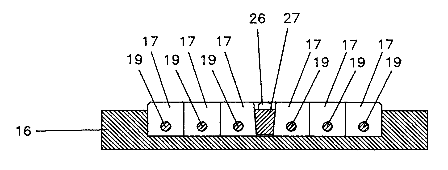
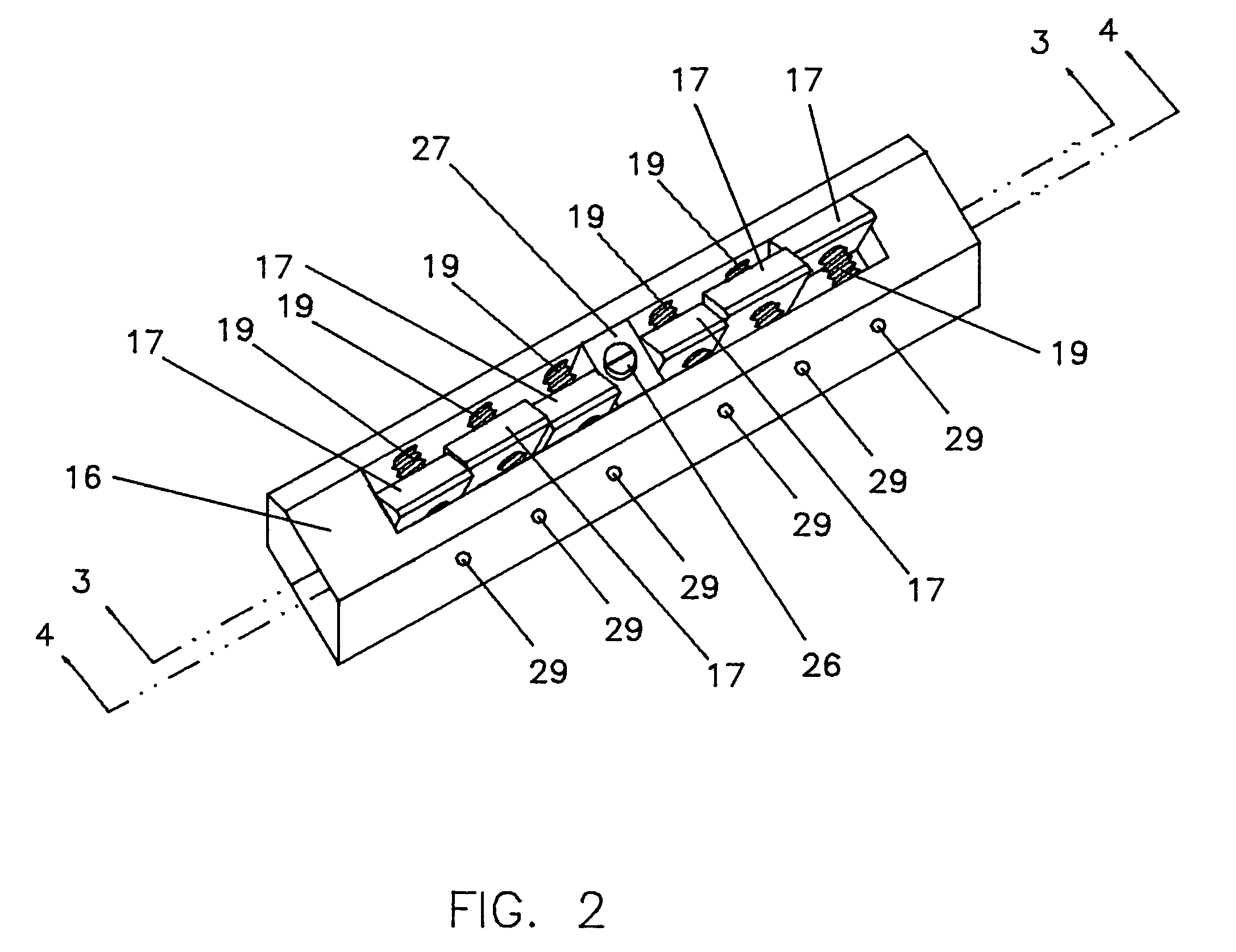
[0044]FIG. 2 shows a front perspective view from above of the preferred embodiment of the invention. The bridge utilizes individual saddles 17 which are retained in positio...


PUM


Abstract

A bridge for providing adjustable active string length on acoustic stringed musical instruments comprised of a concavity surrounding a plurality of individually adjustable saddles that are arranged individually and independently to support each string and be freely moveable into position by an adjustment screw to obtain the harmonic at the 12th fret, and then can be locked in place by action of a contiguous wedge that causes firm contact between the saddles and lateral sides of the concavity.

Description

CROSS-REFERENCE TO RELATED APPLICATIONS[0001]This application claims the benefit of provisional patent application Ser. No. 60 / 646,413, filed Jan. 20, 2005 by the present inventor.FEDERALLY SPONSORED RESEARCH[0002]Not ApplicableSEQUENCE LISTING OR PROGRAM[0003]Not ApplicableBACKGROUND OF INVENTION[0004]1. Field of Invention[0005]This invention relates to adjustable guitar structures and their construction, specifically to provide a method to accurately intonate acoustic guitars.[0006]2. Prior Art[0007]Typically stringed instruments of this type are composed of a series of strings that are strung under tension over a fret board being supported by a nut and saddle or saddles of the bridge. The frets are affixed to the fret board and occupy intermediate positions between the nut and saddle and are used as temporary points of string support to obtain higher frequency tones. To utilize the frets the strings are displaced until contact occurs with the fret. In guitars proper tonal quality...

Claims


Application Information

Patent Timeline
IPC IPC(8): G10D3/04
CPCG10D3/04
Inventor HAGEN, JOHN
Owner HAGEN JOHN
Why Eureka
Try Eureka