Fluid monitoring device

a monitoring device and fluid technology, applied in the direction of flow monitors, traffic control systems, weighing devices, etc., can solve the problems of patient wake-up from anesthesia during surgery, obstructing further fluid delivery through intravenous catheters, and affecting the patient's recovery, so as to increase duties and responsibilities and timely attention

Inactive Publication Date: 2008-02-05
HUNG ORLANDO R +2
View PDF36 Cites 193 Cited by
  • Summary
  • Abstract
  • Description
  • Claims
  • Application Information

AI Technical Summary

Benefits of technology

[0016]The two-sensor system is advantageous since it allows for ratiometric and comparative measurements, thereby limiting the effects of inconsistent shape of the vial, variations in the refractive index of fluids, and ambient light.
[0048]7. A visual and / or audible alarm ensuring timely attention to a situation before it becomes a problem. With reductions in nursing staff, each nurse has increased duties and responsibilities. If the attendant nurse is busy with another task, the alarm will alert her / him of the completion of fluid delivery.

Problems solved by technology

Three potential complications can occur if this termination of fluid delivery is not detected promptly:(1) The back flow of the blood from the venous system of the patient will eventually cause clotting and obstruct further fluid delivery through the intravenous catheter.
This demands the insertion of a new intravenous catheter into the patient's extremities, which is an invasive procedure and can be associated with complications, such as bleeding and infection.(2) If the intravenous fluid is used as a carrier or vehicle for medications, such as intravenous anesthetics, completion of fluid delivery will also stop the administration of medications.
With anesthetics, this lack of administration over time may mean that the patient can wake up from anesthesia during surgery and awareness can occur.
With other types of medication, the administration dosages could suffer.(3) Venous air embolism (VAE) can occur spontaneously due to mishaps with infusion fluid bags.
Patients will be particularly at risk of having a VAE when the infusion of fluid is under pressure for rapid fluid administration, such as patients in shock following trauma.

Method used


Image

  • Fluid monitoring device
  • Fluid monitoring device
  • Fluid monitoring device

Examples


Embodiment Construction

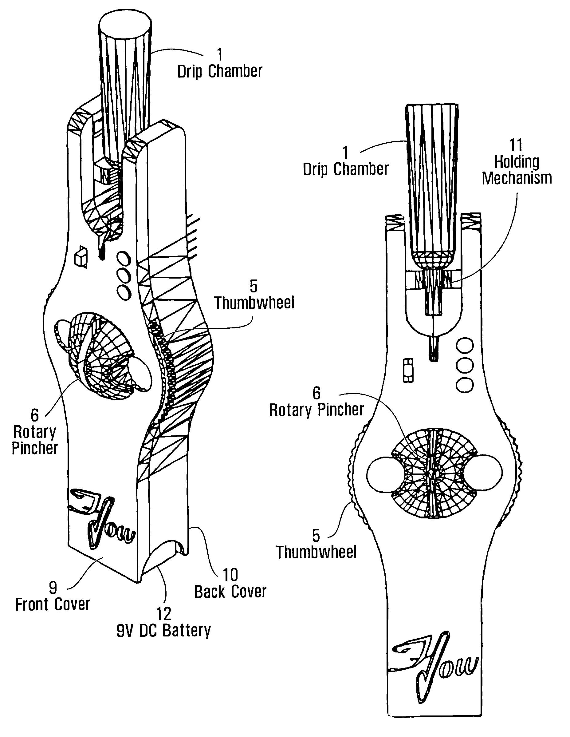
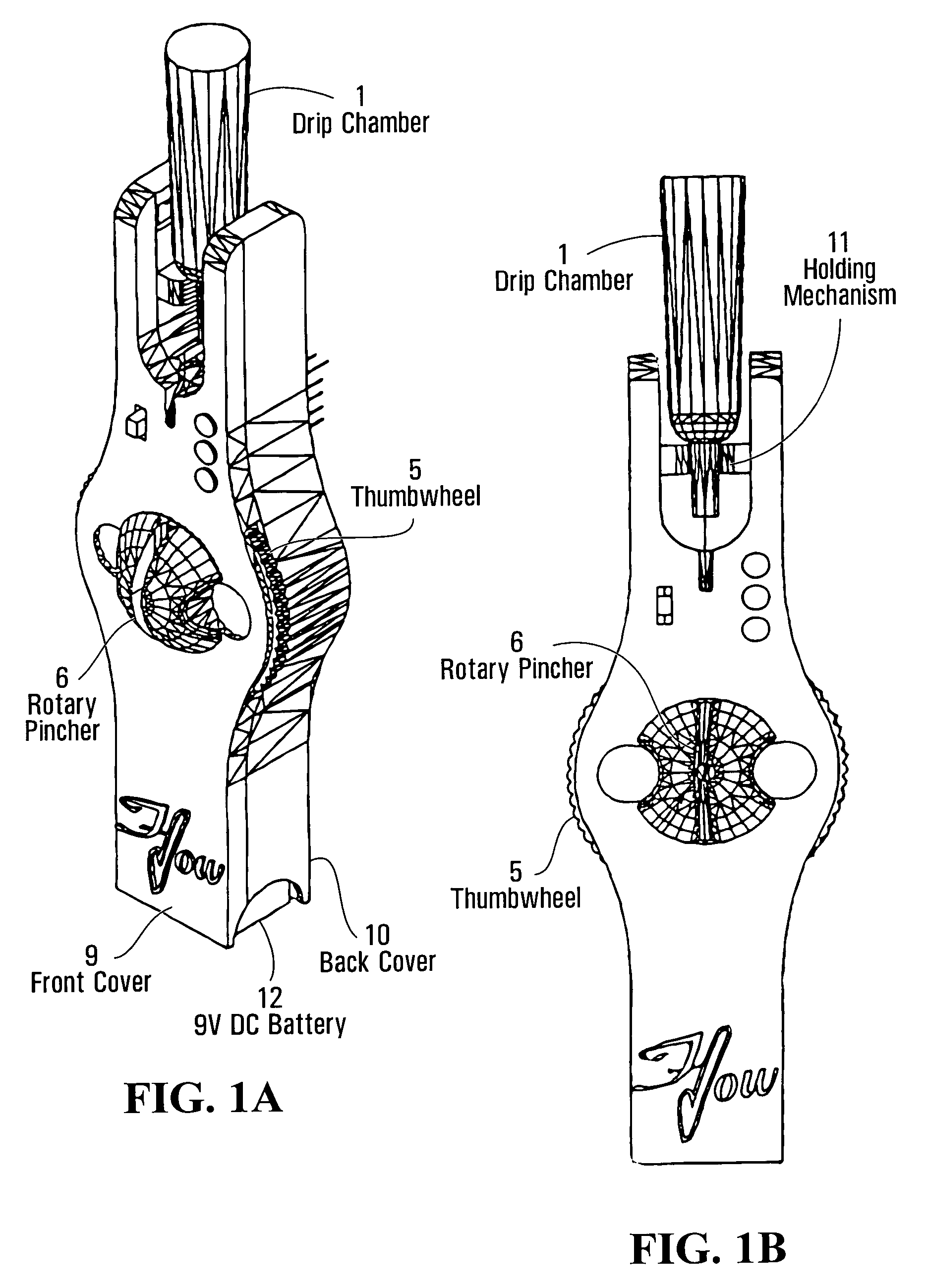
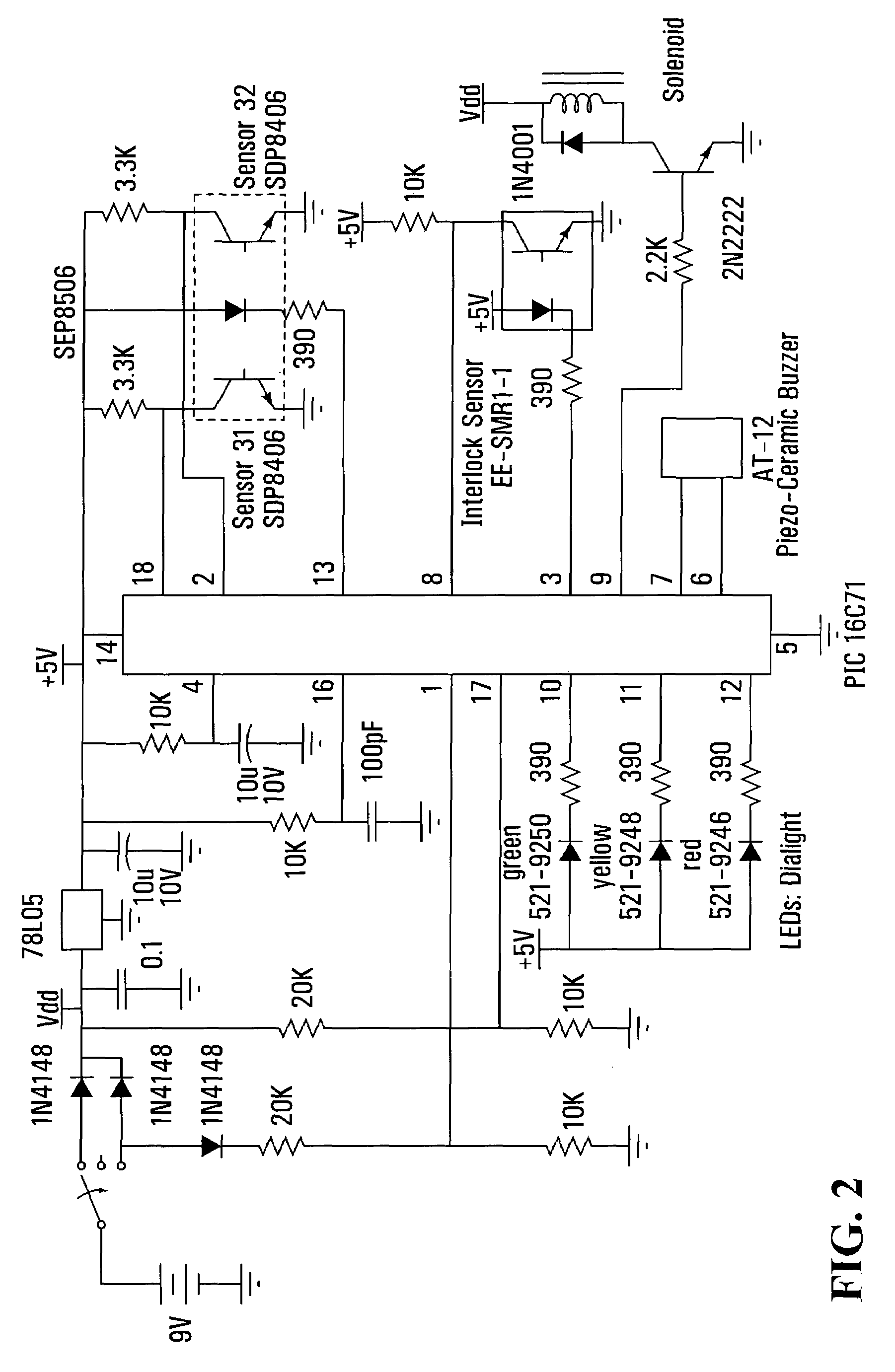
[0054]The following is a description of a preferred embodiment of the invention, embodied in an intravenous monitor. The device includes a drip chamber 1. The chamber is a conventional drip chamber found on most I.V. sets. An infrared emitter 2 and pick-up (sensor) is included as well. There is also a circuit board 3. An electromechanical device 4, preferably a solenoid, is included. Other components such as a thermo strip could be used instead of the solenoid depending on the reaction time required. A thumbwheel 5 is used to manually rotate the rotary pincher 6 to the open position. This motion loads a torsion spring (not shown) that supplies the force to the pincher. The rotary pincher is mounted on the thumbwheel and “pinches” the tube (stopping the flow) as it rotates 90 degrees counterclockwise. This occurs when the signal is received from the circuit board. A lever 7 is attached to the electromechanical device (EMD) and is used to increase the force of the EMD. This allows the...


PUM


Abstract

This invention relates to a device to monitor the administration of a fluid through a conduit, such as intravenous fluid, and detect the completion of fluid delivery by monitoring the fluid level inside a chamber. The device will monitor, through an optical fluid sensor comprising a radiation source, two sensors, a logic means, and an indicating means, the bottom half of any “user supplied” drip chamber that is normally full during the administration of fluids. When the fluid level in the chamber drops below a predetermined level, the indicating means will initiate an electromechanical device that releases a pinching device to occlude the conduit. The pinching device is a rotary pincher that derives its force from a torsion spring and is held in the open position by the electromechanical device.

Description

CROSS-REFERENCE TO RELATED APPLICATION[0001]This application claims benefit of U.S. Provisional Patent Application Ser. No. 60 / 543,552, filed Feb. 12, 2004, entitled “FLUID MONITORING DEVICE”, the contents of which are incorporated by reference.FIELD OF THE INVENTION[0002]This invention relates to a device to monitor the flow of a translucent fluid. In a preferred embodiment, the invention relates to a device to monitor administration of intravenous fluid.DESCRIPTION OF THE PRIOR ART[0003]Intravenous fluid is generally delivered to a patient by dripping it through an intravenous administration set with a drip chamber and tubing, using gravity. When the intravenous fluid container is empty, the drip chamber will run dry and the fluid flow will eventually be stopped. Three potential complications can occur if this termination of fluid delivery is not detected promptly:[0004](1) The back flow of the blood from the venous system of the patient will eventually cause clotting and obstruct...

Claims


Application Information

Patent Timeline
Patent Type & Authority Patents(United States)
IPC IPC(8): G08B21/00A61M37/00G01G23/00
CPCA61M5/1411A61M5/1684A61M5/36A61M39/285
Inventor HUNG, ORLANDO R.GREGSON, PETER H.ROACH, DAVID C.
Owner HUNG ORLANDO R
Why Eureka
Try Eureka