Image processing apparatus and image processing method

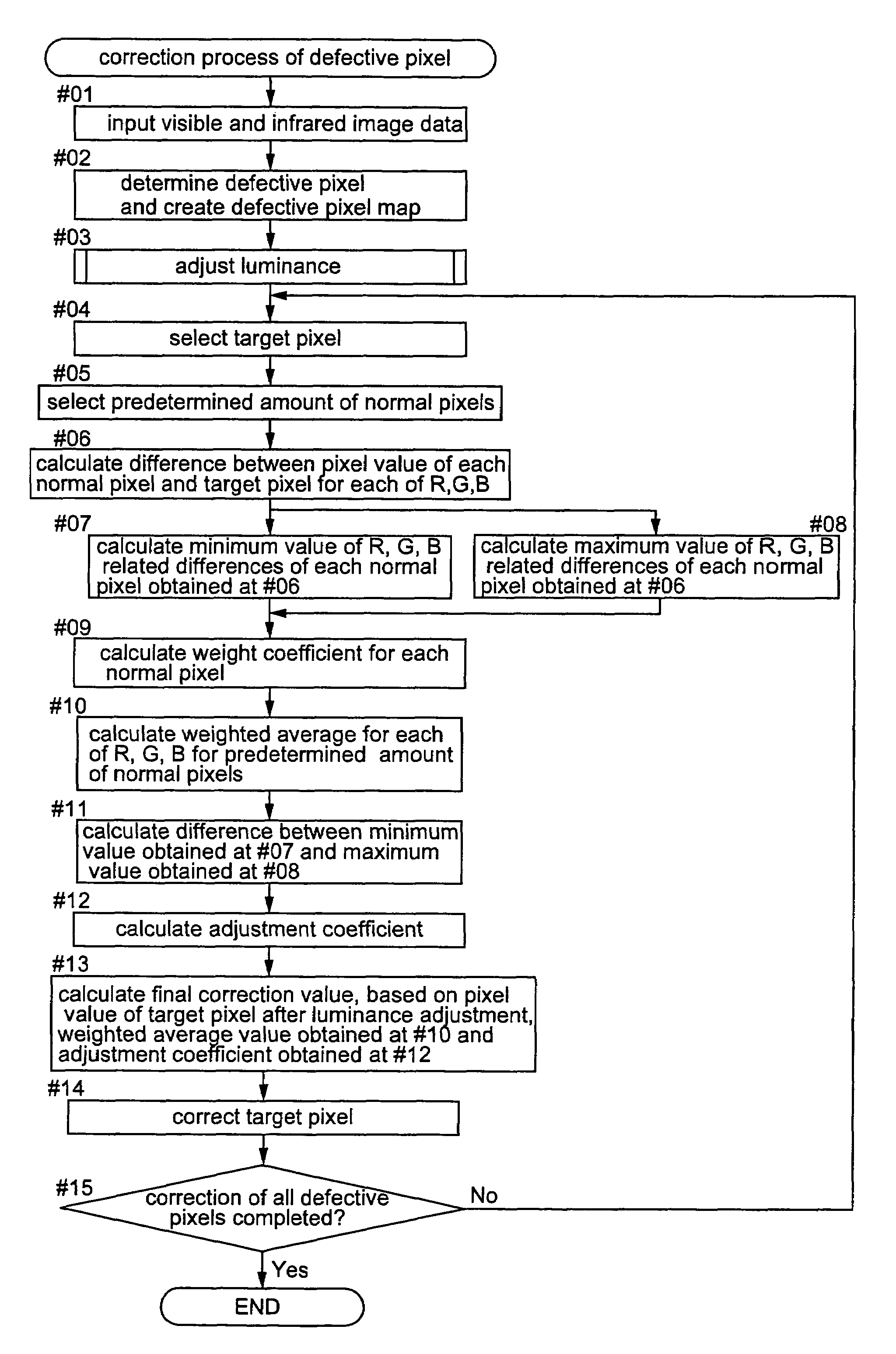
a technology of image processing and image processing, applied in the field of image processing apparatus and image processing method, can solve the problems of inability to correct this defect appropriately, conventional interpolation correction technique, and inability to correct the defective portion properly, so as to reduce the amount of calculation needed, increase processing speed, and correct the defective portion accurately

Inactive Publication Date: 2008-02-05
NORITZ CORP
View PDF12 Cites 16 Cited by
  • Summary
  • Abstract
  • Description
  • Claims
  • Application Information

AI Technical Summary

Benefits of technology

[0011]In view of the above-described state of the art, a primary object of the present invention is to provide an image processing apparatus which is capable of effecting accurate correction of a defective portion by the interpolation technique even when this defective portion contains a complicated image boundary or pattern therein and which is capable also of increasing the processing speed with restricting the amount of calculation needed for the correction.
[0015]a weight coefficient calculating unit configured for obtaining for each color component, a difference between a pixel value of the target pixel whose luminance has been adjusted by the luminance adjusting unit and a corresponding pixel value of each normal pixel selected by the normal pixel selecting unit and subsequently using a minimum value of said differences for the respective color components of each normal pixel, thereby to obtain a weight coefficient common to the respective color components for said each normal pixel, the smaller the minimum value, the greater a weight being provided by said coefficient;
[0019]Then, according to the construction of the present invention, the pixel value for each color component of the target pixel after the luminance adjustment is compared with a pixel value of each corresponding color component of normal pixels adjacent thereto and the correction value for the target pixel is calculated in such a manner that this value is affected more by a normal pixel having similar pixel value(s) for one or two color components than other “non-similar” normal pixels. Hence, the interpolation is effected by using, in the corrected pixel value, a greater portion of the pixel value of the normal pixel which is more similar to the non-defective condition of the target pixel. As a result, the defective pixel can be restored to its non-defective state with greater accuracy. Therefore, even when the defective portion contains a complicated image boundary, pattern etc., accurate correction thereof is made possible, with such boundary or pattern being reflected therein. Further, for the correction of the target pixel, this requires only that the normal pixels selected by the normal pixel selecting unit include as few as 1 to 3 normal pixels which are similar to the non-defective counterpart of the target defective pixel. Thus, accurate correction is possible with a small number of normal pixels as few as e.g. 5 to 10, selected by the normal pixel selecting unit for subsequent calculation. Therefore, the technique proposed by the present invention allows reduction of the required amount of calculation, thus allowing increase in its calculation processing speed. Incidentally, if there is a sufficient margin in the processing speed capacity allowed by the particular apparatus configuration employed, the number of normal pixels to be selected by the normal pixel selecting unit may be increased in order to achieve greater correction accuracy by searching such normal pixels similar to the non-defective condition of the target pixel with greater reliability or by searching a greater number of such normal pixels.
[0021]According to the above-described embodiment, normal pixels closer to the target pixel are positively selected. Hence, pixel values of those normal pixels away from the target pixel are not used or positively excluded for correction of the target pixel. Further, since the search for normal pixels is stopped upon detection of a predetermined amount thereof, the number of pixels used for the calculation can be restricted advantageously thus allowing increased calculation processing speed.
[0031]With the above method proposed by the present invention, the same functions and effects described in connection with the image processing apparatus described hereinbefore can be achieved. Namely, even when a defective portion includes a complicated image boundary (edge) or pattern therein, the method allows accurate correction of such defective portion with reflection of such boundary, pattern or the like therein. The method allows also advantageous reduction in the amount of calculations needed, thereby to increase the calculation processing speed.

Problems solved by technology

However, this luminance adjustment technique is based on an assumption that the pixel values of the respective color components of the defective portion have experienced an equal amount of luminance attenuation.
For this reason, if the amounts of attenuation in the pixel values of the respective color components differ from each other as may happen in the case of a scar in an emulsion surface on the film, the above technique cannot correct this defect appropriately.
However, if the defective portion includes a boundary (edge) or a pattern of the photographic image recorded on the film, such defective portion cannot be properly corrected by the above technique if it simply applies pixel values of adjacent non-defective pixels to the defective portion for its correction.
Yet, this conventional interpolation correction technique exemplified by the Japanese Patent Application “Kokai” No. 2001-78038 discussed above still suffers a problem as follows.
On the other hand, if a complicated image boundary or pattern is present within the defective portion, such defective portion cannot be corrected properly by the above technique which effects the interpolation by using pixel values of normal pixels present along the radial directions.
Especially, appropriate correction becomes even more difficult in case the defective portion is large in its area since the possibility of presence of complicated image boundary or pattern is higher in such large area.
The above technique suffers another problem.
Hence, the technique requires a great amount of calculation for the calculations of the image attribute values and interpolation values.
Accordingly, it is difficult for this technique to increase its processing speed.

Method used


Image

  • Image processing apparatus and image processing method
  • Image processing apparatus and image processing method
  • Image processing apparatus and image processing method

Examples


Embodiment Construction

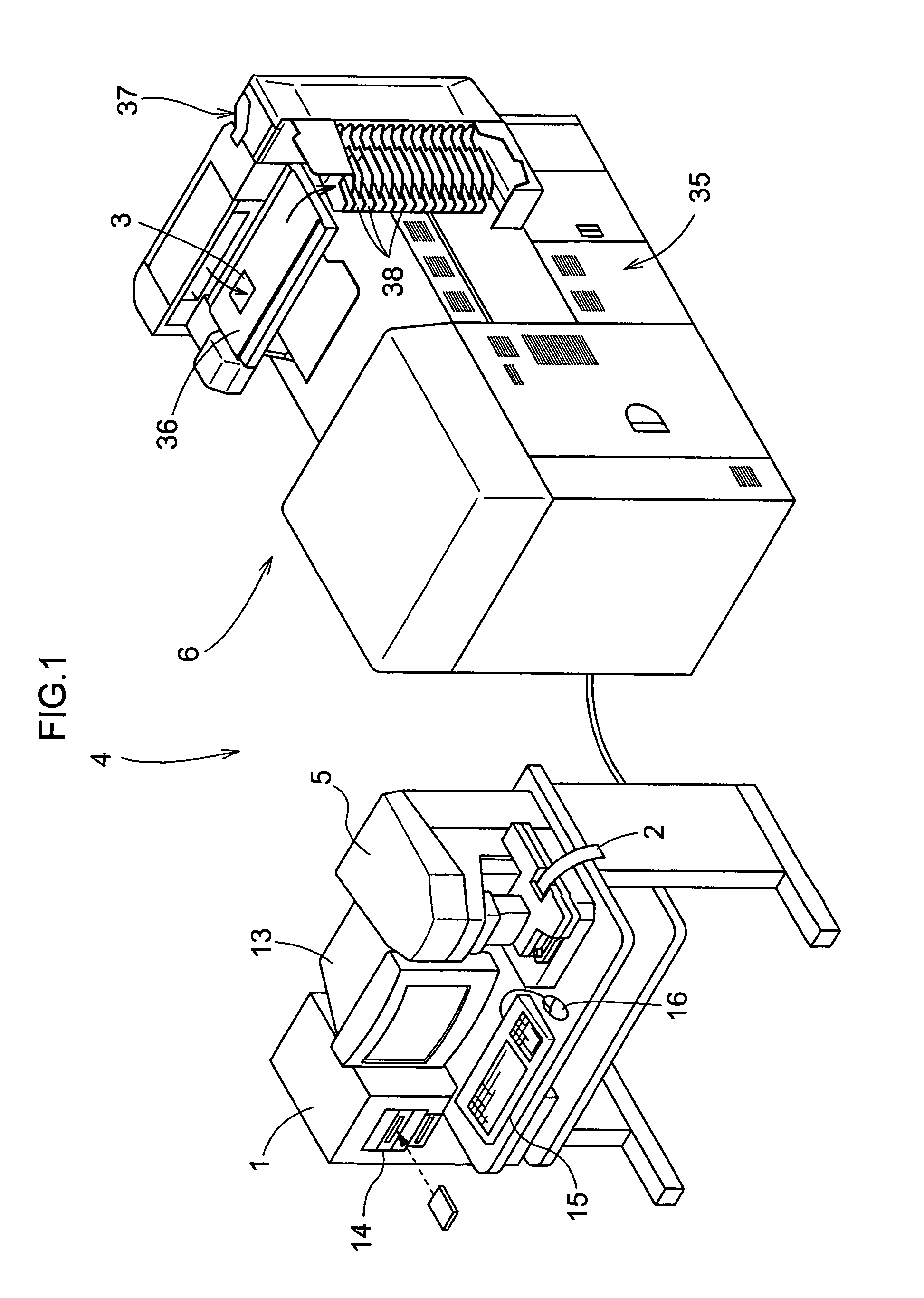
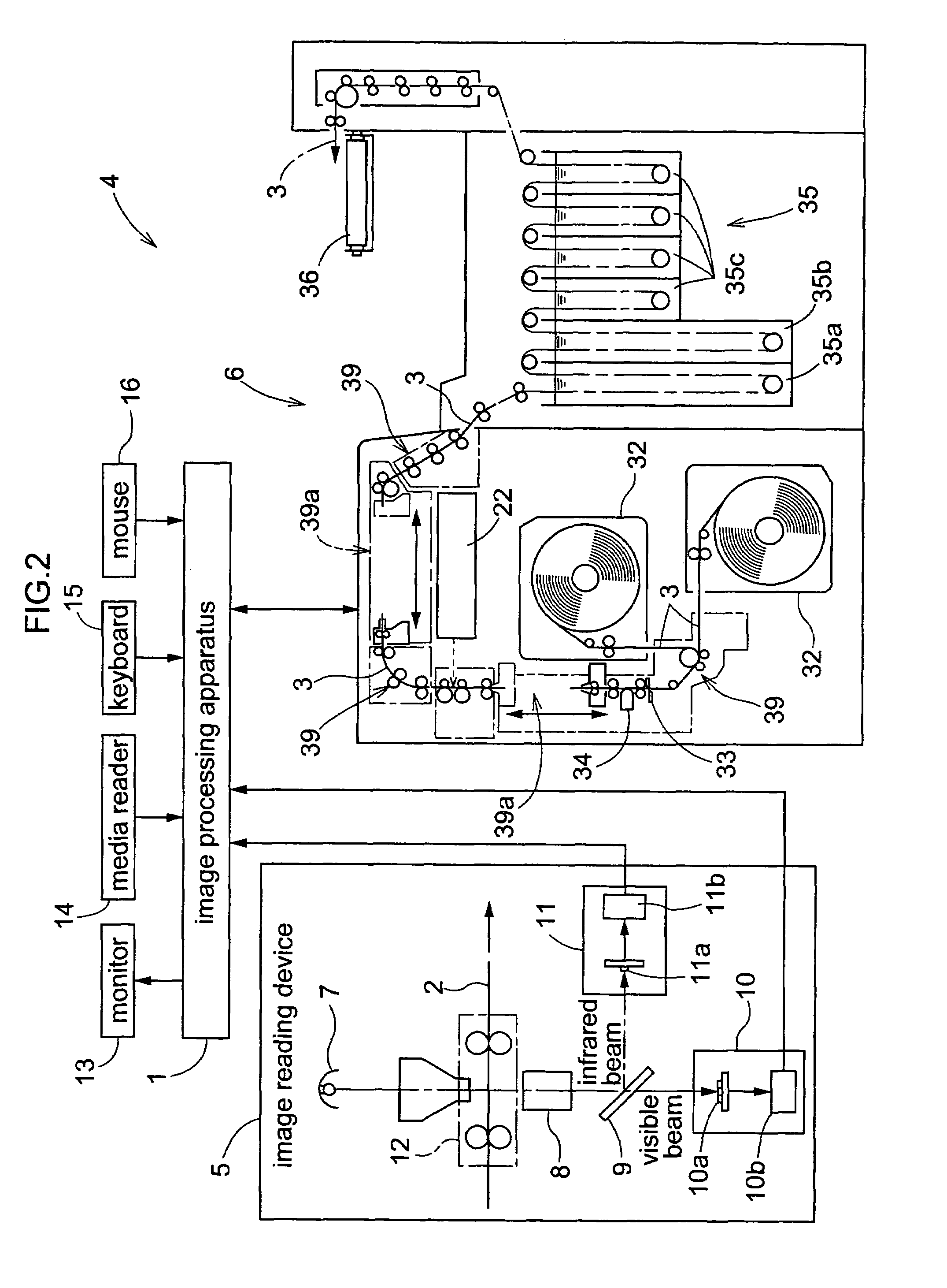
[0039]Next, an embodiment of the present invention will be described with reference to the accompanying drawings. In this embodiment, an image processing apparatus 1 relating to the invention is employed in an image printing system 4 adapted for reading an image from a photographic film 2 and then recording this read film image on a print paper 3. FIG. 1 is a perspective view showing an appearance of the image printing system 4 relating to this embodiment. FIG. 2 is a diagram showing a schematic construction of the image printing system 4 relating to the embodiment. FIG. 3 is a block diagram showing the various functional units of the image processing apparatus 1 relating to the invention.

[0040]As shown in these figures, this image printing system 4 includes an image reading device 5 for reading a photographically recorded image in each frame of the photographic film 2 developed by an unillustrated film developing device as digital image data, the image processing apparatus 1 config...


PUM


Abstract

An image processing method correcting a defective portion in color image data having a plurality of color components. The method includes the steps of adjusting luminance of each defective pixel; selecting a plurality of normal pixels from around a target pixel which is selected from a plurality of defective pixels; obtaining for each color component, a difference between a pixel value of the target pixel whose luminance has been adjusted by the luminance adjusting unit and a corresponding pixel value of each normal pixel selected; obtaining a minimum value of the differences for the respective color components of each normal pixel, thereby to obtain a weight coefficient common to the respective color components for each normal pixel, the smaller the minimum value, the greater a weight being provided by the coefficient; calculating a weighted average value for each color component of the plurality of normal pixels by using the weight coefficient; and correcting the target pixel by using the weighted average value for each color component.

Description

RELATED APPLICATION[0001]Applicant hereby claims priority to Japanese Patent Application No. 2003-307207, filed on Aug. 29, 2003.BACKGROUND OF THE INVENTION[0002]1. Field of the Invention[0003]The present invention relates to an image processing technique for correcting a defective portion in color image data having a plurality of color components. In particular, the invention relates to an image processing technique for effecting an interpolating operation which allows appropriate correction or “retouching” of the image data even when a boundary (edge) or pattern portion of a photographically recorded image is present within its defective portion, by appropriately reflecting such boundary, pattern or the like in the correction.[0004]2. Description of the Related Art[0005]A photographic film may include a defective portion on its surface, such as a scar, dust, dirt, etc. Then, when a photographically recorded image is read from such “defective” film to be printed on a print sheet or...

Claims


Application Information

Patent Timeline
Patent Type & Authority Patents(United States)
IPC IPC(8): G06K9/00G06T5/00H04N1/40G06T1/00H04N1/409H04N1/58H04N1/60H04N1/62H04N5/253H04N9/64
CPCH04N1/4097H04N1/62
Inventor KITA, KOJI
Owner NORITZ CORP
Why Eureka
Try Eureka