

Chevron film cooled wall
a technology of film cooling and chevron, which is applied in the direction of liquid fuel engines, manufacturing tools, lighting and heating apparatus, etc., can solve the problems of reducing engine efficiency, loss of film cooling effectiveness, and flow separation
- Summary
- Abstract
- Description
- Claims
- Application Information
AI Technical Summary
Benefits of technology
Problems solved by technology
Method used
Image

Examples
Embodiment Construction
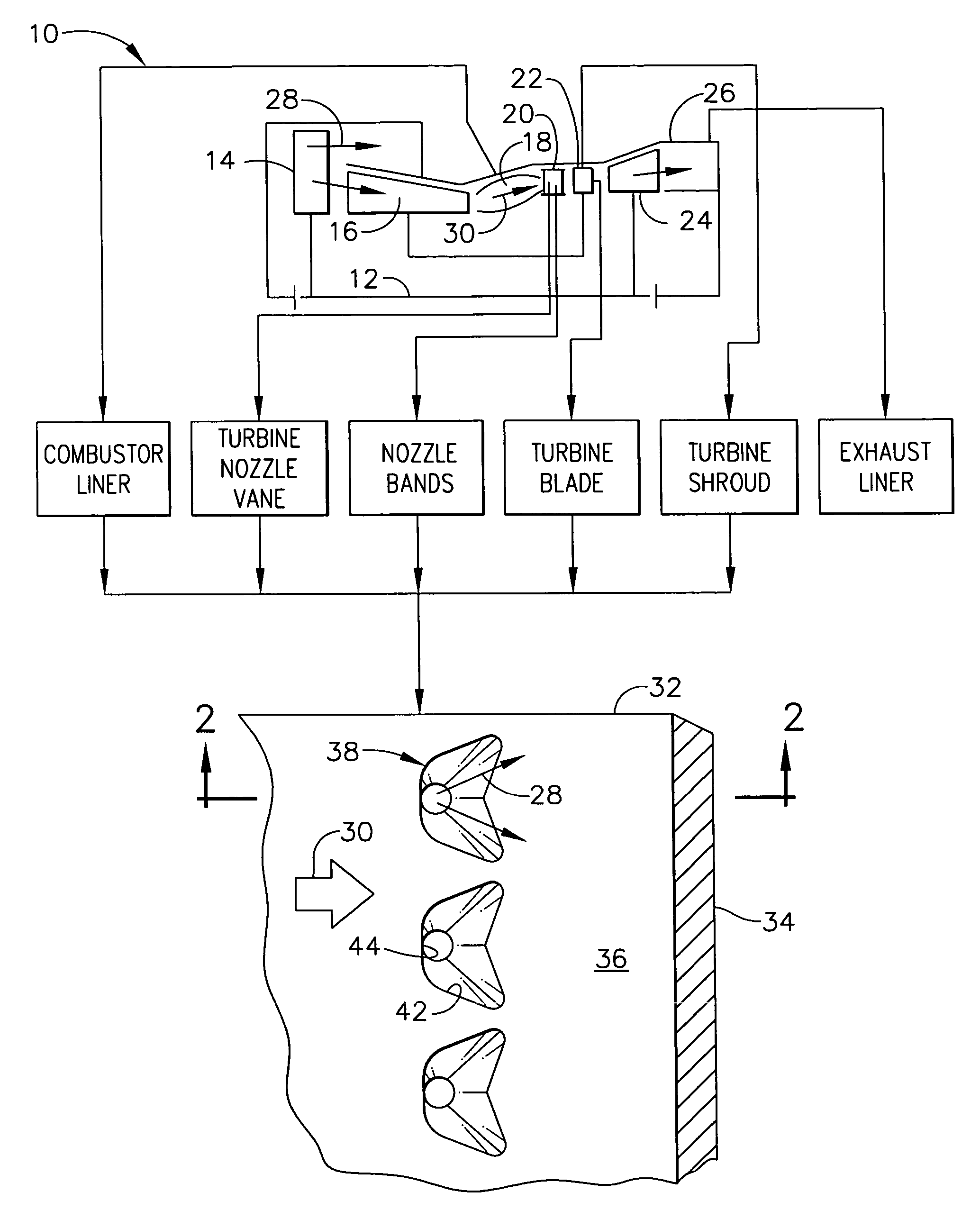
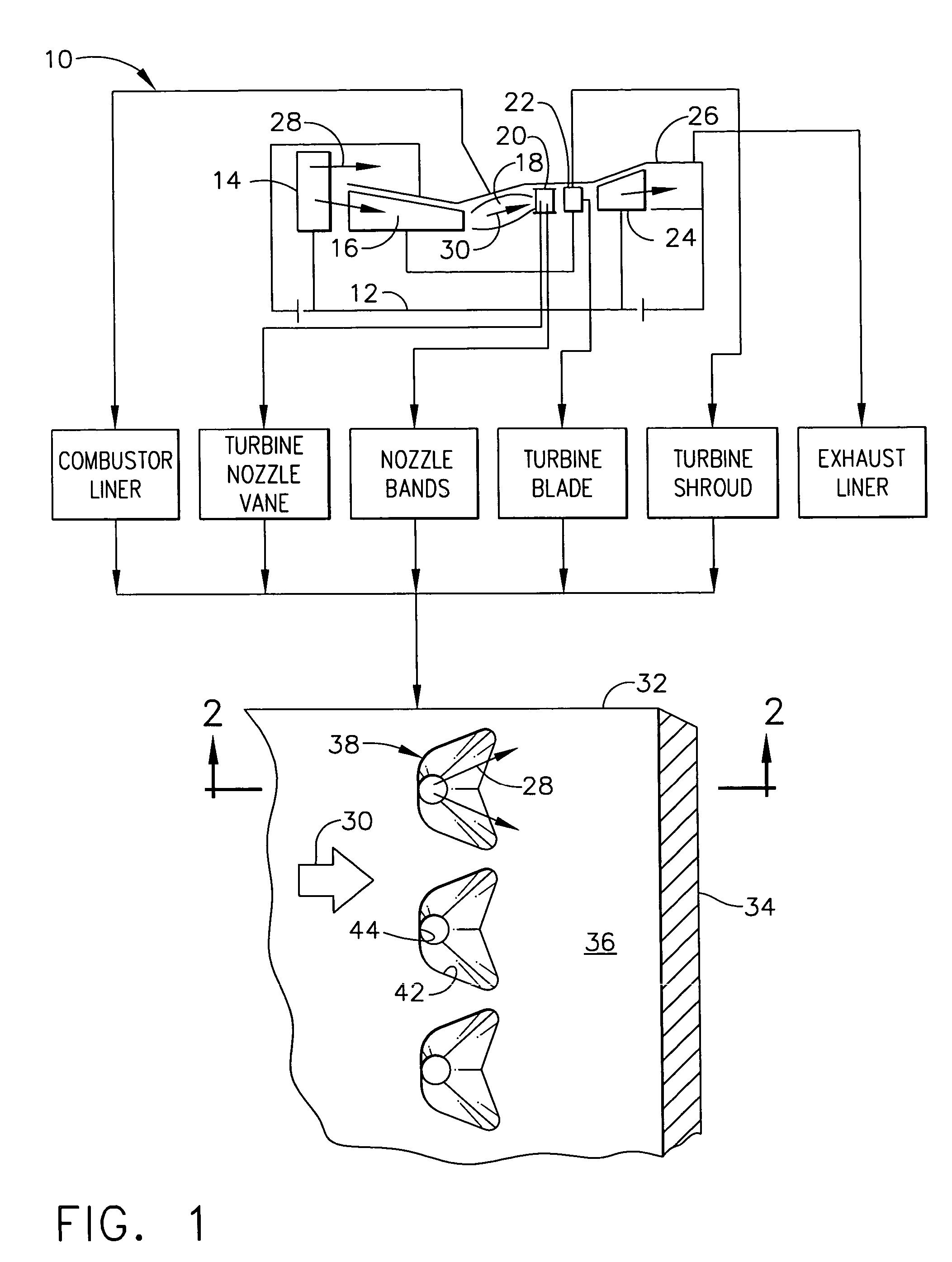
[0028]Illustrated schematically in FIG. 1 is a gas turbine engine 10 which is axisymmetrical about a longitudinal or axial centerline axis 12. The engine includes in serial flow communication a fan 14, multistage axial compressor 16, and an annular combustor 18 followed in turn by a high pressure turbine (HPT) and a low pressure turbine (LPT).
[0029]The HPT includes a turbine nozzle 20 having a row of hollow stator vanes supported in inner and outer nozzle bands. A first stage turbine 22 follows the first stage turbine nozzle and includes a row of hollow rotor blades extending radially outwardly from a supporting rotor disk and surrounded by an annular turbine shroud.
[0030]A low pressure turbine (LPT) 24 follows the high pressure turbine and includes additional nozzles and rotor blades which may or may not include internal cooling circuits depending upon the engine design. An exhaust liner 26 follows the low pressure turbine.
[0031]During operation, ambient air 28 is pressurized by th...
PUM
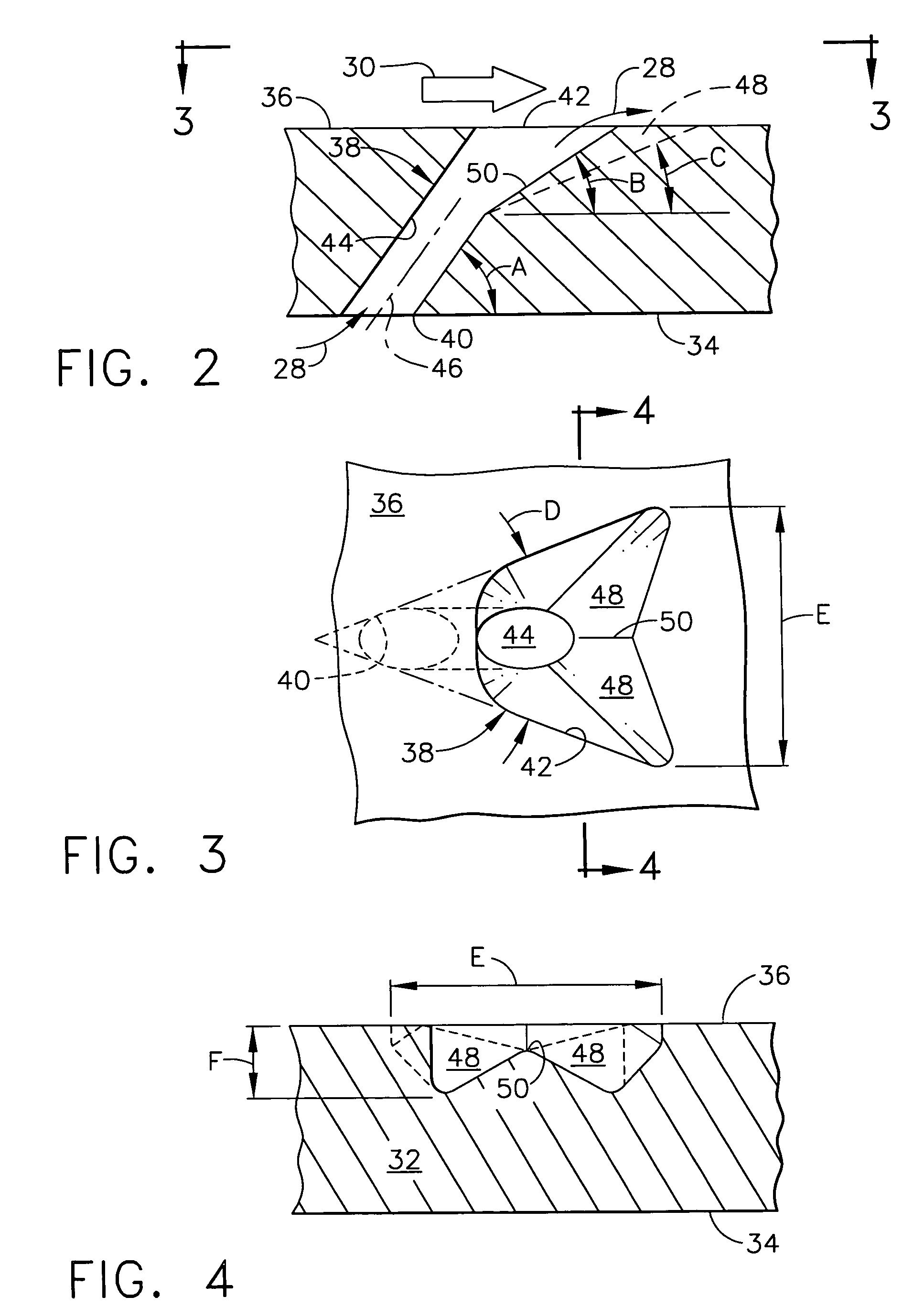
| Property | Measurement | Unit |
|---|---|---|
| diffusion angle | aaaaa | aaaaa |
| inclination angle | aaaaa | aaaaa |
| discharge angle | aaaaa | aaaaa |
Abstract
Description
Claims
Application Information