
Multi-cylinder engine

a multi-cylinder engine and engine technology, applied in the direction of machines/engines, fuel air intakes, combustion-air/fuel-air treatment, etc., can solve the problems of easy damage to the egr cooler, and entanglement problems

Active Publication Date: 2008-02-12
KUBOTA CORP
View PDF12 Cites 25 Cited by
  • Summary
  • Abstract
  • Description
  • Claims
  • Application Information

AI Technical Summary

Benefits of technology

The present invention is about a multi-cylinder engine that can prevent damage to the EGR cooler. The engine has a cylinder head with an intake-air distributing passage wall and an exhaust-gas converging passage wall, with an EGR cooler in between. The EGR cooler spans the front and rear direction of the cylinder block and the exhaust-gas converging passage wall is positioned just above it. This arrangement helps to prevent damage to the EGR cooler and ensures efficient engine performance.

Problems solved by technology

However, in the conventional multi-cylinder engine, the EGR cooler is not protected from above, as indicated in Japanese Patent Application Laid-Open (Kokai) No. 2002-285917 (see FIG. 1), to result in entailing problems.
The EGR Cooler is Easily Damaged.
Therefore, at the time of producing the engine or performing the maintenance, if parts, tools or the like substances fall in an upper area of the engine, those substances are likely to collide against the EGR cooler from above with the result of easily damaging the EGR cooler.

Method used


Image

  • Multi-cylinder engine
  • Multi-cylinder engine
  • Multi-cylinder engine

Examples


Embodiment Construction

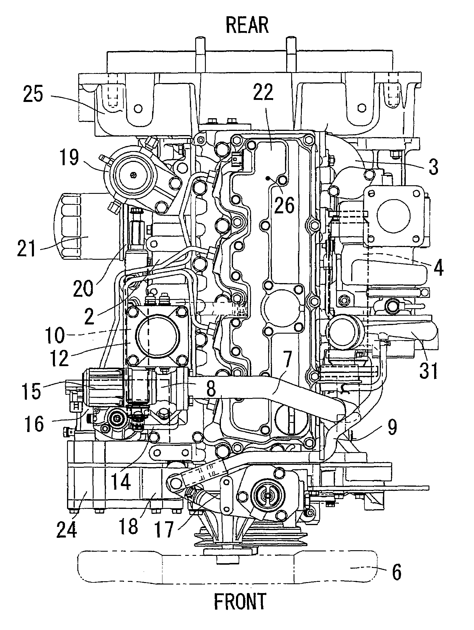
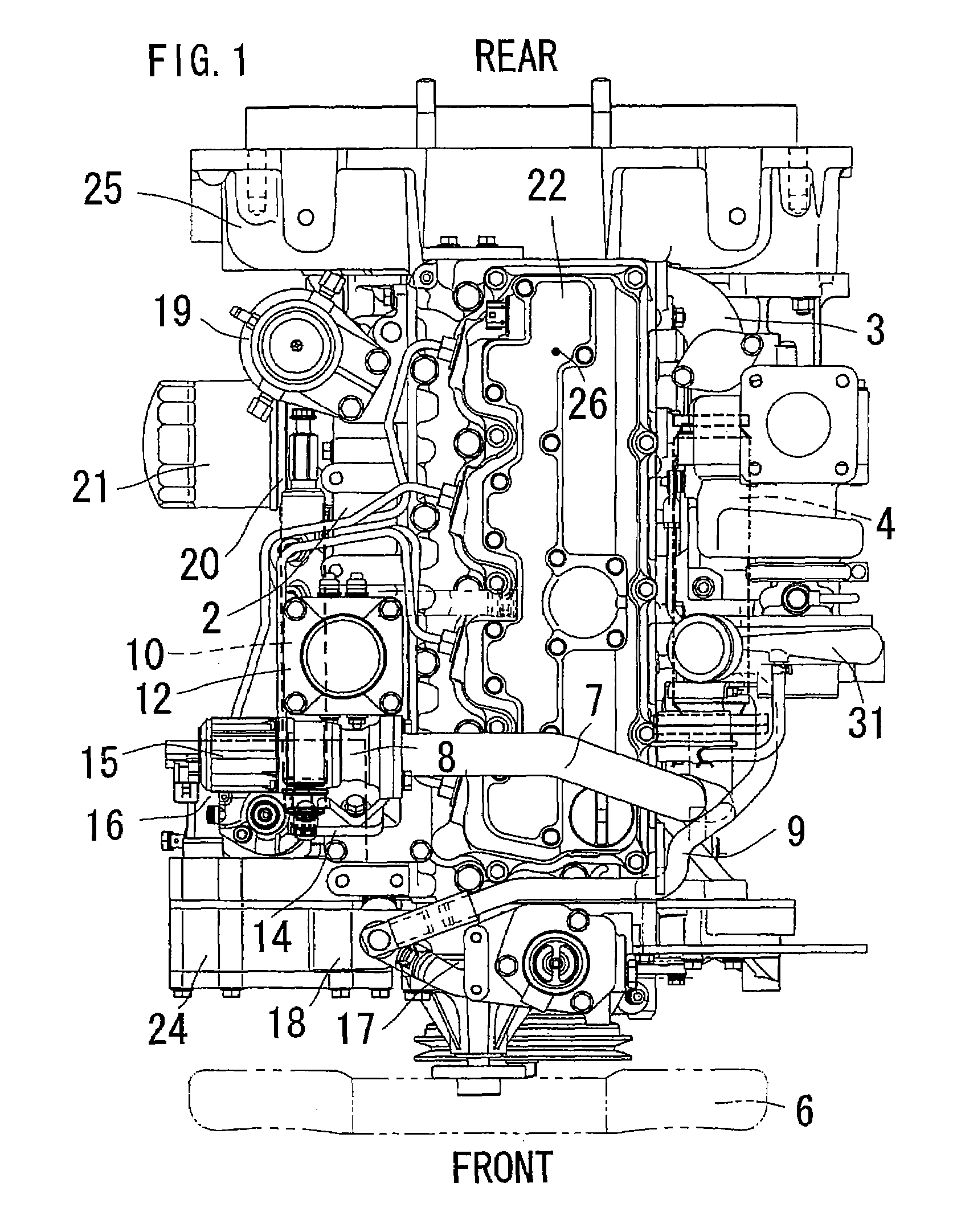
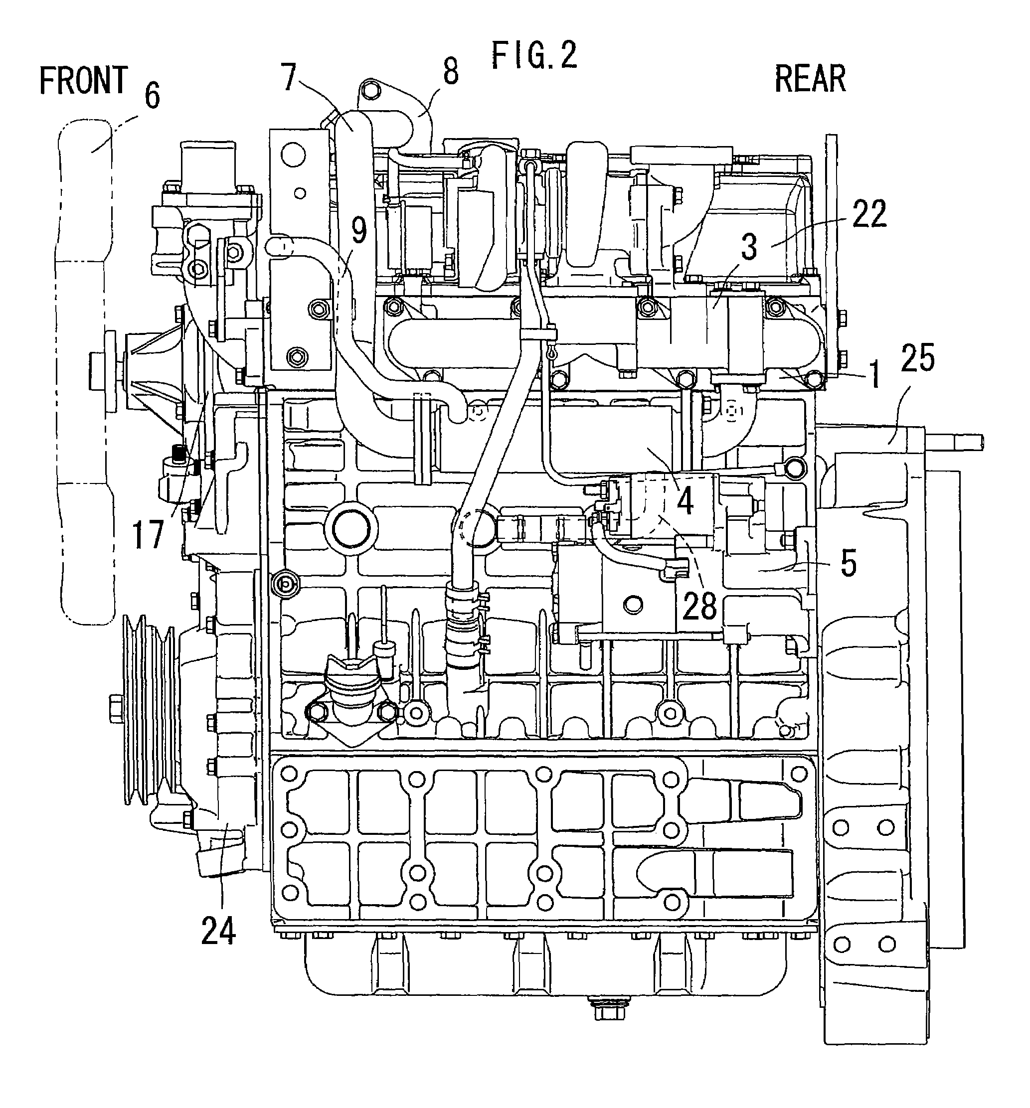
[0047]An embodiment of the present invention is explained based on the attached drawings. FIGS. 1 to 4 show an engine according to the embodiment of the present invention. In this embodiment, an explanation is given for a water-cooled vertical straight multi-cylinder diesel engine.

[0048]The embodiment of the present invention is outlined as follows.

[0049]As shown in FIGS. 2 to 4, a cylinder head 1 is assembled to an upper portion of a cylinder block 5 and has an upper portion to which a head cover 22 is assembled. The cylinder block 5 has a lower portion to which an oil pan 23 is assembled and has a front portion to which a gear case 24 is assembled. Further, the cylinder block 5 has a rear portion to which a flywheel housing 25 is assembled.

[0050]A cooling water pump 17 is attached to the cylinder block 5 above the gear case 24. The cooling water pump 17 has an input shaft to which an engine cooling fan 6 is attached. The cooling water pump 17 and the engine cooling fan 6 are drive...


PUM


Abstract

A multi-cylinder engine wherein a direction in which a crank shaft spans is a front and rear direction and a widthwise direction of a cylinder head (1) perpendicular to the front and rear direction is a lateral direction, the multi-cylinder engine comprising the cylinder head (1) which has one lateral side to which an intake-air distributing passage wall (2) is attached and has the other lateral side to which an exhaust-gas converging passage wall (3) is attached, an EGR cooler being interposed between an exhaust-gas converging passage and an intake-air distributing passage. In this multi-cylinder engine, the EGR cooler (4) spans in the front and rear direction laterally of a cylinder block (5) and the exhaust-gas converging passage wall (3) is positioned just above the EGR cooler (4). Preferably, an EGR gas lead-out pipe 7 conducted out of the EGR cooler (4) is arranged rearwards of an engine cooling fan (6) so that the engine cooling air produced by the engine cooling fan (6) might blow against the EGR gas lead-out pipe (7).

Description

BACKGROUND OF THE INVENTION[0001]The present invention concerns a multi-cylinder engine and more particularly, relates to a multi-cylinder engine able to inhibit an EGR cooler from being damaged.[0002]There is a conventional example of the multi-cylinder engine which comprises a cylinder head having one lateral side surface onto which an intake-air distributing passage wall is attached and having the other lateral side surface onto which an exhaust-gas converging passage wall is attached with an EGR cooler interposed between an exhaust-gas converging passage and an intake-air distributing passage, as well as the present invention, on the assumption that a direction where a crank shaft spans is taken as a front and rear direction and that a widthwise direction of the cylinder head perpendicular to the front and rear direction is deemed as a lateral direction.[0003]However, in the conventional multi-cylinder engine, the EGR cooler is not protected from above, as indicated in Japanese ...

Claims


Application Information

Patent Timeline
Patent Type & Authority Patents(United States)
IPC IPC(8): F02M25/07F02B47/08F02M35/10
CPCF01P1/06F02M25/0735F02M25/0737F02M25/0748F02M55/025Y02T10/121F02M25/0747F02M26/30F02M26/32F02M26/41F02M26/42
Inventor HATAURA, KIYOSHIMIYAZAKI, MANABUOKAJIMA, TOSHINORITAKII, OSAMUKAMIYAMA, MITSURUMURATA, MUTSUMIMIKUMO, HIROSHINAKAMURA, YASUSHI
Owner KUBOTA CORP
Learn More