Crane supporting apparatus

a technology of supporting apparatus and crane, which is applied in the direction of cranes, etc., can solve the problems of crane leveling and maneuvering, trucking is typically difficult to level or stabilize on uneven or sloped construction site surfaces, and trucks are often unable to traverse soft ground surfaces

Inactive Publication Date: 2008-02-12
RHODES LESTER KENT
View PDF22 Cites 47 Cited by
  • Summary
  • Abstract
  • Description
  • Claims
  • Application Information

AI Technical Summary

Benefits of technology

[0020]A further object of the present invention is to provide such a crane support which is further adapted for control

Problems solved by technology

A drawback or disadvantage of such configuration relates to crane leveling and maneuvering.
Trucks typically are difficultly leveled or stabilized upon uneven or sloped construction site surfaces.
Also, trucks often are unable to traverse soft ground surfaces, and are unable to maneuver between c

Method used


Image

  • Crane supporting apparatus
  • Crane supporting apparatus
  • Crane supporting apparatus

Examples


Embodiment Construction

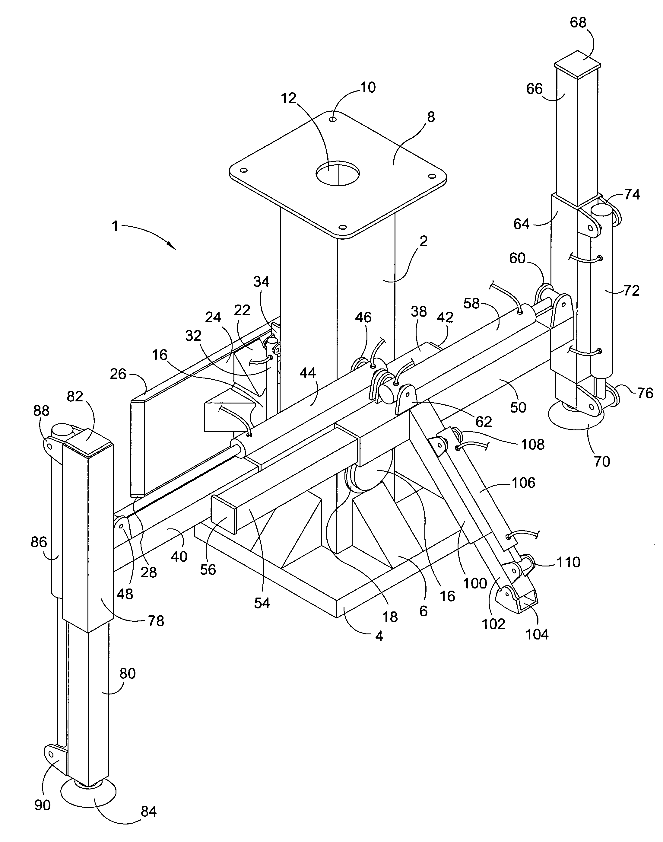
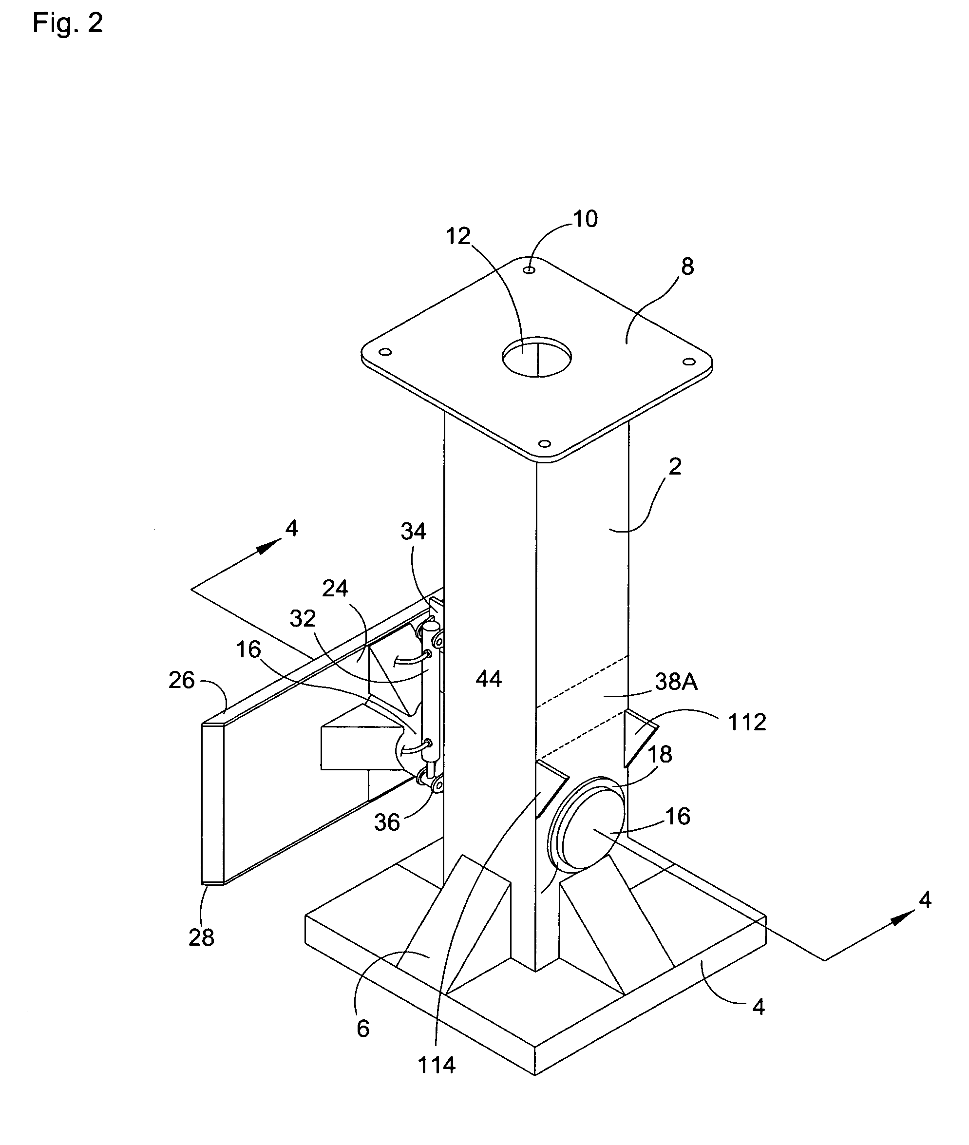
[0026]Referring now to the drawings, and in particular to FIG. 1, a preferred embodiment of the instant inventive crane support is referred to generally by Reference Arrow 1. A major structural component of the crane support 1 is a pedestal 2, preferably comprising 1′×1′ steel square tubing. The pedestal 2 has a crane mounting plate 8 fixedly welded to its upper end, such plate 8 having bolt receiving apertures 10 extending therethrough, and having a hydraulic line receiving aperture 12 extending centrally therethrough. An enlarged base 4 is preferably fixedly welded to the lower end of the pedestal 2, the base 4 preferably being stiffened and supported by triangulating braces 6. Referring further to FIG. 3, the crane mounting plate is similarly supported by triangulating braces 7.

[0027]Referring simultaneously to FIGS. 1, 2, and 4, an axle receiving bearing sleeve 14 extends through and is fixedly welded within the pedestal 2, such bearing sleeve 14 slidably and rotatably receiving...


PUM


Abstract

A crane support consisting of a steel square tubing pedestal having an apertured mounting plate fixedly attached to its upper end, and having an enlarged base fixedly attached to its lower end; an axle, the pedestal being mounting rotatably upon the axle; an auxiliary implement mounting frame fixedly attached to a rearward end of the axle, such mounting plate being adapted for attachment to skid steer loader lift arms and bucket dumping rams; a pair of telescoping outriggers fixedly attached to and extending laterally from the pedestal, each outrigger arm having downwardly extendable and upwardly retractable foot fixedly attached to its distal end; a plurality of hydraulic cylinders operatively connected to the telescoping outriggers and to the feet for alternating lateral and vertical extensions and retractions; and a hydraulic cylinder connected operatively to the pedestal for alternately locking the pedestal against rotation with respect to the mounting frame and permitting such rotation.

Description

FIELD OF THE INVENTION[0001]This invention relates to heavy construction equipment. More particularly, this invention relates to machinery adapted for transporting, supporting, positioning, and stabilizing load lifting cranes.BACKGROUND OF THE INVENTION[0002]Load lifting cranes are commonly mounted upon the load bearing bed of a common truck. Such a configuration advantageously provides for stable vertical support of the crane. A drawback or disadvantage of such configuration relates to crane leveling and maneuvering. Trucks typically are difficultly leveled or stabilized upon uneven or sloped construction site surfaces. Also, trucks often are unable to traverse soft ground surfaces, and are unable to maneuver between closely spaced obstacles. Such disadvantages prevent truck mounted load lifting cranes from being utilized at many construction sites.[0003]Construction site locations which are unreachable via a truck are commonly reachable via more mobile and maneuverable constructio...

Claims


Application Information

Patent Timeline
IPC IPC(8): B66C23/80
CPCB66C23/80
Inventor RHODES, LESTER KENT
Owner RHODES LESTER KENT
Why Eureka
Try Eureka