Pressurizing lid structure of a kneader

a lid structure and kneader technology, applied in the field of kneaders, can solve the problems of uneven quality, affecting the work efficiency of the machine, and affecting the quality of the kneader, so as to reduce the clearance, prevent defective dispersion of the filler, and stabilize the blending ratio of the filler

Active Publication Date: 2008-02-12
MORIYAMA
View PDF16 Cites 3 Cited by
  • Summary
  • Abstract
  • Description
  • Claims
  • Application Information

AI Technical Summary

Benefits of technology

[0008]The objective of the present invention, realized in view of the above-described problems of conventional kneaders, is to provide a kneader capable of eliminating a cleaning process in the kneading process by preventing gushing of the filler through the clearance between the mixing tank and the pressurizing lid, stabilizing the blending ratio of the filler, and preventing defective dispersion due to fall and mixing of the filler after the completion of kneading, for promoting improvement of dispersion and uniformity of kneaded materials such as rubber, plastics, etc. as well as stability of quality.
[0013]According to the first aspect of the present invention, in a kneader comprising a mixing tank for storing the kneaded material, a pair of rotors disposed in parallel for kneading the kneaded material stored in the mixing tank, and a pressurizing lid inserted slidably in the opening at the top of the mixing tank, the sliding portion of the pressurizing lid against the mixing tank is divided into a plurality of stages (upper, lower), a packing is disposed for reducing the clearance between the respective pressurizing lids and the side wall of the mixing tank as much as possible, and an air reservoir is formed between the upper and lower lids. This construction makes it possible to control the force of the powder gushing through the air reservoir and effectively prevent gushing to outside from the packing disposed in the pressurizing lid at the top stage, even in case the powder gushed out from the packing disposed on the pressurizing lid of the lower stage, thus enabling to eliminate the cleaning process in the kneading process, stabilize the blending ratio of the filler, and prevent defective dispersion of the filler due to fall and mixing after the completion of kneading, for promoting improvement of dispersion and uniformity of kneaded material as well as stability of quality.
[0015]According to the second aspect of the present invention, in a kneader comprising a mixing tank for storing the kneaded material, a pair of rotors disposed in parallel for kneading the kneaded material stored in the mixing tank, and a pressurizing lid inserted slidably in the opening at the top of the mixing tank, the sliding portion of the pressurizing lid against the mixing tank is divided into a plurality of stages (upper, lower), a packing is disposed for reducing the clearance between the lower pressurizing lid and the side wall of the mixing tank as much as possible, on the lower pressurizing lid, and an air reservoir is formed between the upper and lower lids. This construction makes it possible to control the force of the powder gushing through the air reservoir and effectively prevent gushing to outside through the clearance between the lid at the top stage and the side wall of the mixing tank, even in case the powder gushed out from the lid of the lower stage, thus enabling to eliminate the cleaning process in the kneading process, stabilize the blending ratio of the filler, and prevent defective dispersion of the filler due to fall and mixing after the completion of kneading, for promoting improvement of dispersion and uniformity of kneaded material as well as stability of quality.
[0016]In this case, by realizing the top side face and bottom side face, which constitute the opposing face of the upper lid and the lower lid, as sloped faces opening toward the outside, and forming said two sloped faces in a way to be continuous on a curved side face, it becomes possible to allow the current of the air containing the filler, which penetrated from the lower-stage lid, to draw an arc smoothly at the portion of curved face, thus providing a kneader capable of greatly reducing the amount of powder adhering and accumulating on the side face between the lids.

Problems solved by technology

However, if the filler gushes out to the top part of the pressurizing lid 4, it not only stains the surrounding area but also presents a problem of remarkably lowering the productivity, because it becomes necessary to set a cleaning process of the filler which accumulated at the top face 42 of the pressurizing lid 4 and at the peripheral part 1a of the opening at the top of the mixing tank 1 in the kneading process, and stop the equipment operation for it.
Moreover, another problem was that a change of blending ratio is produced in proportion to the spouted filler, causing unevenness of quality among batches, or the filler which accumulated at the top face 42 of the pressurizing lid and at the peripheral part 1a of opening at the top of the mixing tank drops and is mixed in the material at the time of discharge of the material after the completion of kneading, causing a defective dispersion, etc.

Method used


Image

  • Pressurizing lid structure of a kneader
  • Pressurizing lid structure of a kneader
  • Pressurizing lid structure of a kneader

Examples


embodiment 1

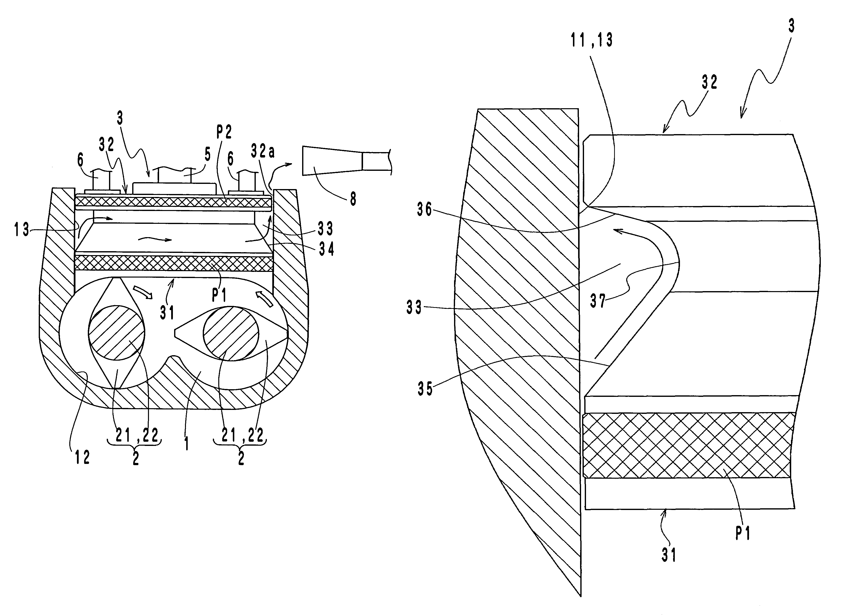
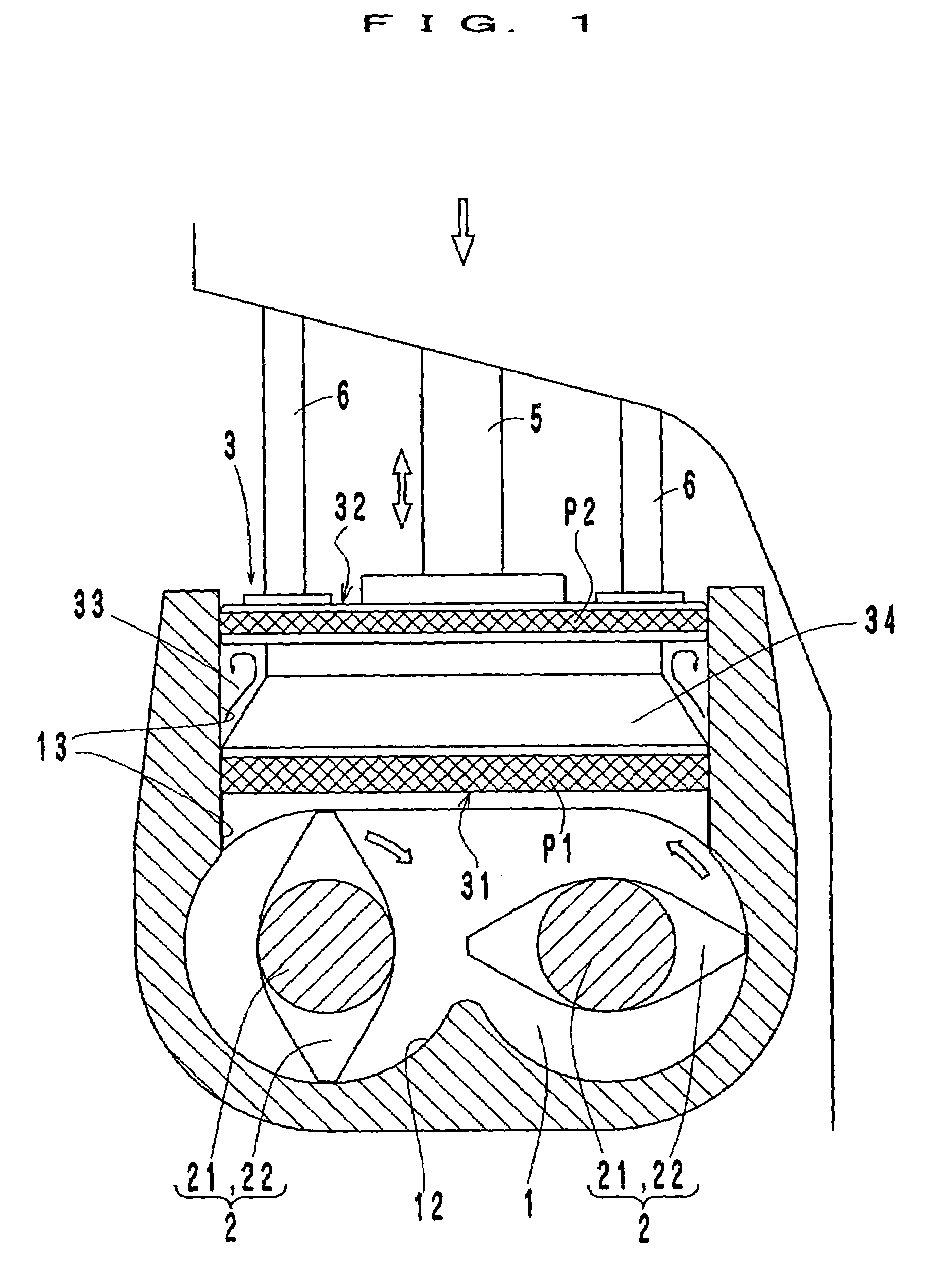
[0049]In this way, the kneader of this embodiment prevents gushing of the filler to outside through the clearance other than the clearance 32a between the mixing tank 1 and the pressurizing lid 3, by means of an air reservoir 33 formed with the lower-stage lid 31 and the upper-stage pressurizing lid 32 disposed in the pressurizing lid 3 in the same way , but the filler gushes to outside only through the clearance 32a between the mixing tank 1 and the pressurizing lid 3, in the case where the dose of the powder in the kneaded material is particularly high. However, since the filler which gushed out can be effectively sucked by the duct 8 disposed over the clearance 32a, it becomes possible to eliminate the cleaning process in the kneading process, prevent defective dispersion of the filler due to fall and mixing after the completion of kneading, and promote improvement of dispersion and uniformity of kneaded materials as well as stability of quality.

[0050]FIG. 6 to FIG. 8 indicate an...

first embodiment

[0060]This kneader is an improved type of the kneader in the first embodiment, and shows an example in which the air reservoir 33 is constructed in the shape of U, without constructing the air reservoir 33 on the side X where the cleaning is difficult because no sufficient cleaning space for the pressurizing lid can be secured, from the viewpoint of kneader structure.

[0061]Similarly, in the case where two sides of the pressurizing lid 3 are difficult to clean, it may be all right to construct the air reservoir 33 in the shape of L only on two sides available for cleaning, without constructing the air reservoir 33 on the sides difficult to clean.

[0062]However, because the air reservoir 33 can effectively prevent gushing of the filler to outside when it is provided in an annular shape, the air reservoir 33 shall preferably be provided on all of the 4 sides as much as possible, in an annular shape (donut shape).

[0063]So far, an explanation has been given of the kneader of the present i...


PUM

PropertyMeasurementUnit
stabilityaaaaaaaaaa
pressurizing forceaaaaaaaaaa
inner volumeaaaaaaaaaa

Abstract

In a kneader having a mixing tank 1 for storing the kneaded material, a pair of rotors, 2 disposed in parallel for kneading the kneaded material stored in the mixing tank 1, and a pressurizing lid 3 inserted slidably in the opening at the top of the mixing tank 1, the sliding portion of the pressurizing lid 3 against the mixing tank 1 is divided into a plurality of stages (upper, lower), packings P1, P2 are disposed for reducing the clearance between the respective pressurizing lids and the side wall of the mixing tank as much as possible, and an air reservoir 33 is formed between the upper and lower lids 31, 32.

Description

BACKGROUND OF THE INVENTION[0001]The present invention concerns a kneader, and more specifically a kneader capable of eliminating a cleaning process in the kneading process, by preventing gushing of the filler through the clearance between the mixing tank and the pressurizing lid, stabilizing the blending ratio of the filler and preventing defective dispersion due to fall and mixing of the filler after the completion of kneading, for promoting improvement of dispersion and uniformity of kneaded materials such as rubber, plastics, etc. as well as stability of quality.[0002]Conventionally, a kneader is constructed by disposing a pair of rotors, 2 in a mixing tank 1 as shown in FIG. 11, in a way to turn inward mutually, forming a rotor blade 22 (twisted blade) by twisting the rotor so that the kneaded material may constantly be forwarded to the inner side (center side) of the mixing tank 1, and further disposing a pressurizing lid 4 at the top of the mixing tank 1, to have the kneaded ...

Claims


Application Information

Patent Timeline
Patent Type & Authority Patents(United States)
IPC IPC(8): B29B7/24
CPCB29B7/183B29B7/24F16J1/008B29B7/248B29B7/7495
Inventor MATSUMOTO, SHINICHI
Owner MORIYAMA
Why Eureka
Try Eureka