Method for shielding flat circuit body, shielded flat circuit body, and wiring harness

a flat circuit body and flat circuit technology, applied in the direction of contact members penetrating/cutting insulation/cable strands, insulated conductors, cables, etc., can solve the problem of low process efficiency, improve process efficiency, reduce the kind of flat circuit body components, and improve the reliability of the assembly process

Active Publication Date: 2008-02-12
YAZAKI CORP
View PDF10 Cites 77 Cited by
  • Summary
  • Abstract
  • Description
  • Claims
  • Application Information

AI Technical Summary

Benefits of technology

[0020]As mentioned above, according to the present invention, by piercing the joint terminal through the flat circuit body and the shield film, the conductor of the flat circuit body and the shield film are connected electrically, so that for assembling the shielded flat circuit body, the process of ultrasonic welding is not required. Thereby, the method of shielding the flat circuit body according to the present invention can improve the efficiency of process for assembling the shield film. Even if an insulation material exists between the conductor of the flat circuit body and the shield film, the joint terminal is pierced through the flat circuit and the shield film, so that the flat circuit body and the shield film can be fixed securely and the conductor of the flat circuit body and the shield film can be connected securely and electrically through the joint terminal. Thus, the method of shielding the flat circuit body according to the present invention can improve reliability of the process of assembling the shield film.
[0021]Since the joint terminal connects conductors of the plurality of flat circuit body to each conductor, an additional component is not required. Thereby, according to the method of shielding, kind of components for the flat circuit body can be reduced, and an efficiency of assembling the shield film can be improved.
[0022]Since the clamp blade of the connecting terminal and the joint blade of the joint terminal are pierced through the flat circuit body in the same direction, the process for connecting the conductor of the flat circuit body and the connecting terminal and the process for connecting the conductor of the flat circuit body and shield film and fixing the flat circuit body and the shield film with the joint terminal can be acted simultaneously. Therefore, according to the method of shielding, the efficiency of assembling the shield film can be improved, and the reliability of assembling the shield film can be improved also.
[0023]Since the flat circuit body and the shield film are pierced by the joint terminal for connecting them electrically, the process of ultrasonic welding is not required. Even if an insulation material exists between the conductor of the flat circuit body and the shield film, the joint terminal is pierced through the flat circuit body and the shield film, so that the flat circuit body and the shield film can be fixed securely and the conductor of the flat circuit body and the shield film can be connected securely and electrically through the joint terminal. Thus, the shielded flat circuit body according to the present invention can improve reliability of the process of assembling the shield film.
[0024]Since the joint terminal connects conductors of the plurality of flat circuit body to each conductor, an additional component is not required. Thereby, according to the shielded flat circuit body, kind of components for the flat circuit body can be reduced, and an efficiency of assembling the shield film can be improved.
[0025]Since the clamp blade of the connecting terminal and the joint blade of the joint terminal are pierced through the flat circuit body in the same direction, the process for connecting the conductor of the flat circuit body and the connecting terminal and the process for connecting the conductor of the flat circuit body and shield film and fixing the flat circuit body and the shield film with the joint terminal can be acted simultaneously. Therefore, according to the shielded flat circuit body, the efficiency of assembling the shield film can be improved, and the reliability of assembling the shield film can be improved also.

Problems solved by technology

Thus, assembling process is increased and an efficiency of acting the process is low.

Method used


Image

  • Method for shielding flat circuit body, shielded flat circuit body, and wiring harness
  • Method for shielding flat circuit body, shielded flat circuit body, and wiring harness
  • Method for shielding flat circuit body, shielded flat circuit body, and wiring harness

Examples


Embodiment Construction

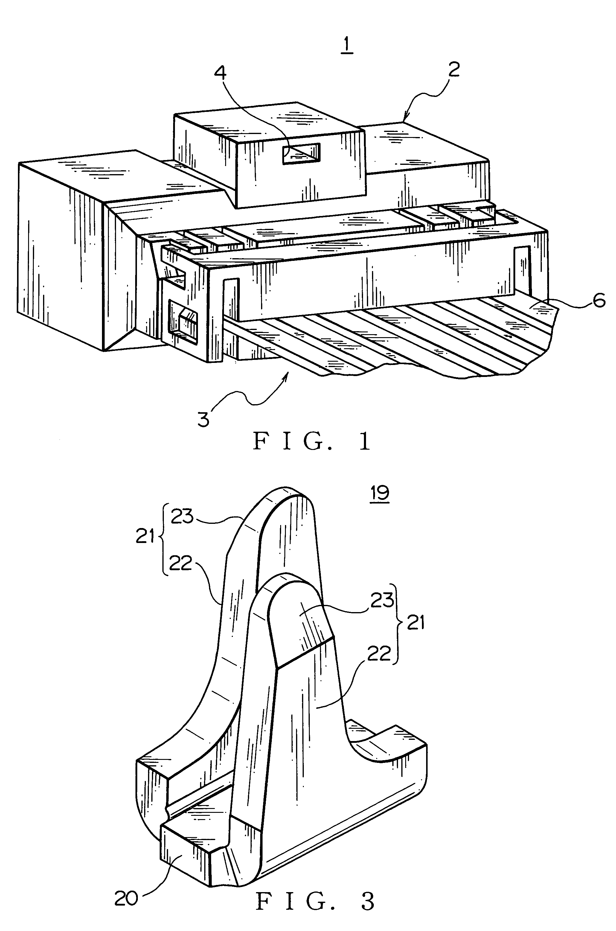
[0040]A method of shielding a flat circuit body, a shielded flat circuit body and a wiring harness of each embodiment according to the present invention will be described with reference to FIGS. 1-7. A wiring harness 1 includes a connector housing 2 (call female housing hereafter) and a shielded flat circuit body 3.

[0041]The female housing 2 is made of insulating synthetic resin, and formed into a flat box-shape. The female housing 2 includes a terminal receiving section (not shown) for receiving a later-described connecting terminal 7 and a lock hole 4. A plurality of the terminal receiving sections extending linearly is arranged in parallel to each other. Each terminal receiving section receives the connecting terminal 7 therein, so that the female housing 2 receives the plurality of the connecting terminals 7. The lock hole 4 is formed by recessing from an outer surface of the female housing 2. A lock projection (not shown) of a connector housing (not shown) of a later-described ...


PUM


Abstract

A method of shielding a flat circuit body and a wiring harness including the shielded flat circuit body, the shielded flat circuit body of the wiring harness includes a FFC having insulator covering around a conductor, a shield film covering the FFC and a connecting terminal. A clamp blade is pierced through an end of the FFC and is bent so as to connect electrically to the conductor. A joint blade extending perpendicularly from a joint terminal, which connects a plurality of conductors to each other, is pierced through the shield film and the FFC in the same direction of piercing the clamp blade, and is bent so as to connect the conductor and the shield film electrically.

Description

[0001]The priority application Number Japan Patent Application 2005-149510 upon which this patent application is based is hereby incorporated by reference.BACKGROUND OF THE INVENTION[0002]1. Field of the Invention[0003]This invention relates to a shielding method of a flat circuit body, such as a FPC(Flexible Printed Circuit) and a FFC (Flexible Flat Cable), to be covered by a shield film as a shielded flat circuit body and a wiring harness having the shielded flat circuit body.[0004]2. Description of the Related Art[0005]Various electronic apparatuses are installed in a car as a vehicle. In the car, a wiring harness 50 (shown in FIG. 10) is wired for transmitting electric power from a power supply, such as a battery, and control signals from a controller to the electronic apparatus. The wiring harness 50 shown in FIG. 10 includes a connector housing (not shown) and a shielded FFC 51. The connector housing receives a later-described terminal 53 of the shielded FFC 51 therein.[0006]T...

Claims


Application Information

Patent Timeline
Patent Type & Authority Patents(United States)
IPC IPC(8): H01R4/24
CPCH01R12/616H01R12/68H05K1/0218H05K9/0024H01R12/594H05K1/0393H05K3/326H05K3/4046H05K2201/0715H05K2203/1189H01B7/0861
Inventor KUMAKURA, HIDETOASAKURA, NOBUYUKI
Owner YAZAKI CORP
Why Eureka
Try Eureka