Method of making a fluted filter media for air filter

a filter media and flute technology, applied in the field of fluted filter media, can solve the problems of increasing pressure differential, inadequate filter surface area, and prior attempts to improve the filter surface area for a given filter volume have not been entirely successful, so as to achieve the effect of improving flow characteristics

Inactive Publication Date: 2008-02-12
DONALDSON CO INC
View PDF65 Cites 127 Cited by
  • Summary
  • Abstract
  • Description
  • Claims
  • Application Information

AI Technical Summary

Benefits of technology

[0011]The present invention is directed to a fluted filter device, and in particular, to fluted filter media with improved flow characteristics.

Problems solved by technology

A common problem with filters is inadequate filter surface area.
Prior attempts to improve filtering surface area for a given filter volume have not been entirely successful.
This restriction may cause the velocity of flow to increase in order to pass through the filtering media, thereby increasing the pressure differential across the filter which may cause additional problems in the system.
Most permeable filter media does not provide structural support so that the filters require housings for supporting the filtering material.
This increases manufacturing costs as well as the mass and size of the filter.
The sealed upstream ends of flutes provide a substantial blockage of the flow, and when combined with the filter material, more than half of the available cross sectional area of the fluid flow is blocked.

Method used


Image

  • Method of making a fluted filter media for air filter
  • Method of making a fluted filter media for air filter
  • Method of making a fluted filter media for air filter

Examples


first embodiment

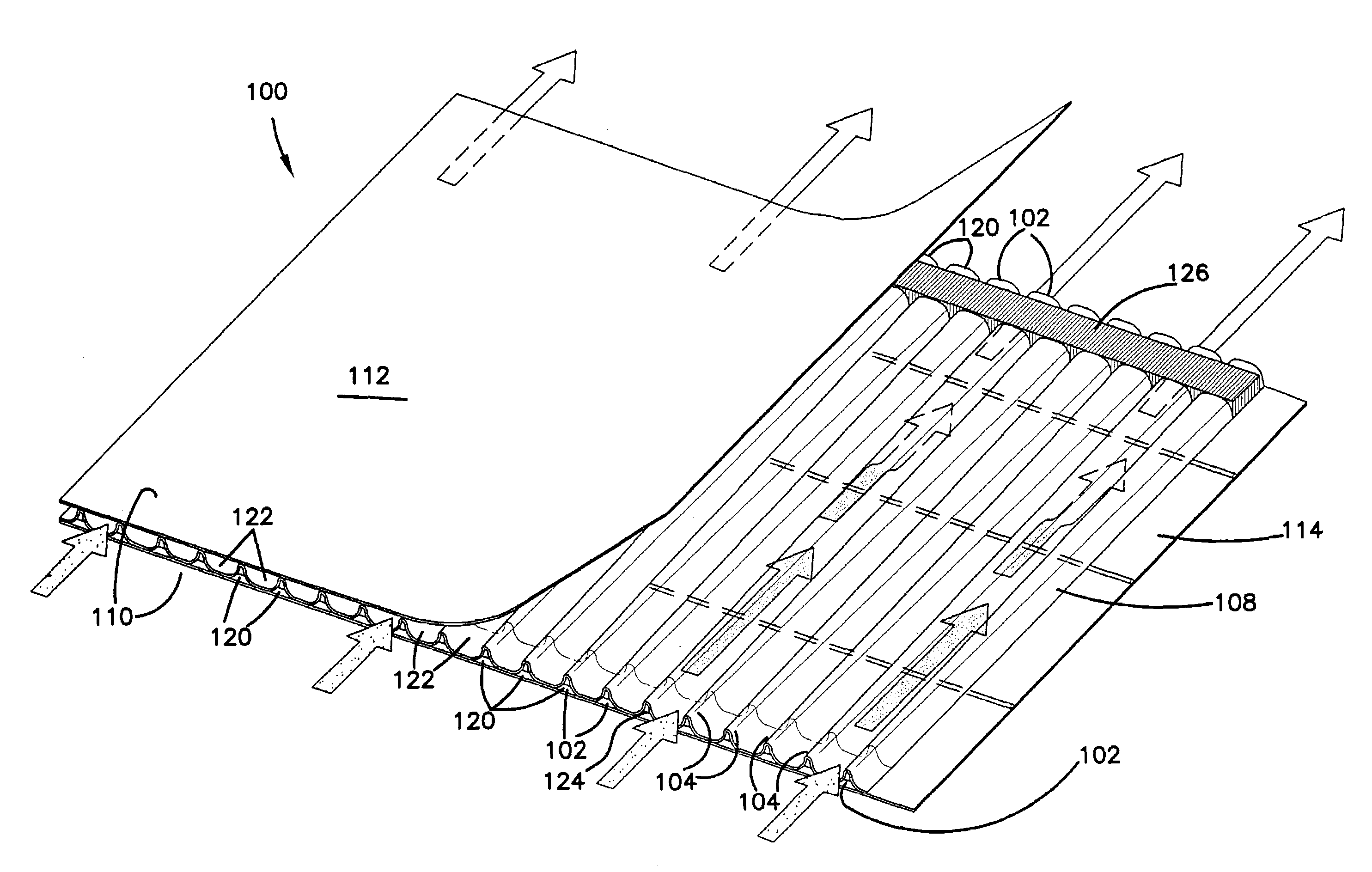
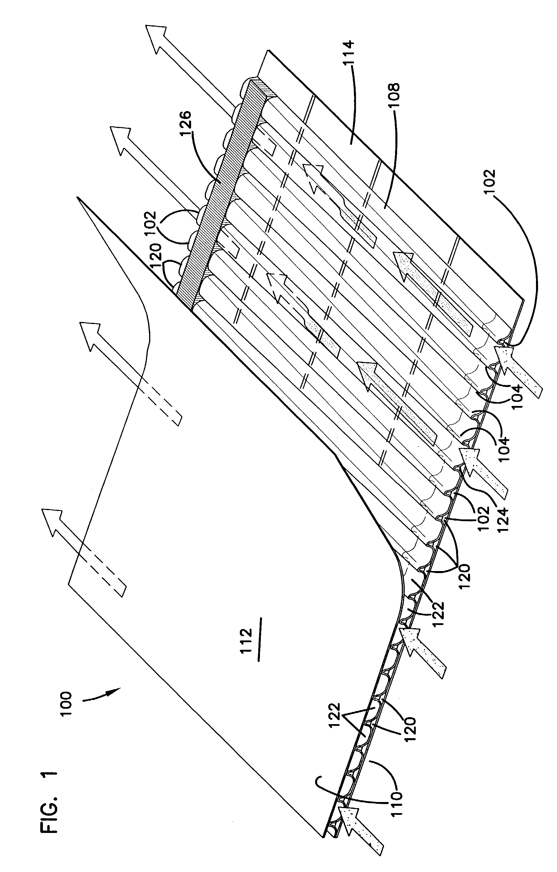
[0034]Referring now to the drawings, and in particular to FIG. 1, there is shown a portion of a layer of double-faced permeable fluted filter media, generally designated 100. the fluted filter media 100 includes a multiplicity of tapered flute chambers 102. The flute chambers 102 are formed by a center fluting sheet 108 forming alternating peaks 104 and troughs 106 between facing sheets 110, including a first facing sheet 112 and a second facing sheet 114. The troughs 106 and peaks 104 divide the flutes 102 into an upper row and lower row. In the configuration shown in FIG. 1, the upper flutes form flute chambers 122 closed at the downstream end, while upstream closed end flute chambers 120 are the lower row of flute chambers. The fluted chambers 120 are closed by first end bead 124 completely filling a section of the upstream end of the flute between the center fluting sheet 108 and the second facing sheet 114. Similarly, a second end bead 126 closes the downstream end of alternati...

second embodiment

[0041]Referring now to FIG. 6, there is shown filter media, generally designated 200, having asymmetric flutes according to the principles of the present invention. The filter media 200 includes asymmetric flutes 202 forming substantially narrower peaks 204 and widened arcing troughs 206. The radius of the arc of the peaks 204 is less than the radius of the arc of the troughs 206 of the asymmetric flutes 202. The filter media 200 includes a center sheet 208 and facing sheets 210, including a first upper facing sheet 212 and a second lower facing sheet 214.

[0042]The facing sheets 210 are connected by upstream beads 224 and downstream beads 226. In this manner, the sheets 208, 212 and 214 form chambers 220 having their upstream ends closed and chambers 222 having their downstream ends closed.

[0043]It can be appreciated that with the configuration shown in FIG. 6, the upstream portion of the filter media 200 intercepting flow includes an enlarged opening for the chambers 222. In this m...

fourth embodiment

[0049]Referring now to FIG. 14, there is shown the present invention with fluted filter media 400. The fluted filter media 400 is similar to other fluted filter media, but the fluted filter media 400 has a modified upstream edge and bead configuration, as explained hereinafter. As shown in FIG. 14, the fluted filter media 400 includes flutes 402 having peaks and troughs with flutes 420 closed upstream and flutes 422 closed downstream. However, unlike other fluted filters having alternating chambers sealed at the extreme upstream face of the filter media, the flutes 420 include a bead 424 sealing off the flute chamber which is recessed from the upstream edge of the filter media 400. The flutes 422 have beads 426 which ate at the downstream end.

[0050]The filter media 400 provides performance advantages as it can be appreciated that large particles 1000 may accumulate at the upstream face of the filter media. As shown in FIG. 14, if the particles 1000 are large enough, some of the flut...


PUM

PropertyMeasurementUnit
lengthaaaaaaaaaa
surface areaaaaaaaaaaa
volumeaaaaaaaaaa

Abstract

Fluted filter media includes filter material having a plurality of flutes formed therein having alternating ends of adjacent flutes closed to force fluid through filter material. A first embodiment of the filter media includes tapered flutes which have the open ends of the flutes larger in cross-section than the closed flutes, wherein the upstream open flutes converge toward the downstream end and the upstream closed end flutes diverge toward the downstream end. A second embodiment includes filter media which is asymmetric formed with dissimilar upstream and downstream flute cross-sections with larger flute openings to the upstream side of the filter. A third embodiment includes filter media with an upstream edge crushed to improve flow at the upstream edge. A fourth embodiment includes filter media with the upstream sealing material recessed from the upstream edge for reducing effects from blockages at the upstream edge of the filter.

Description

[0001]The application is a divisional of application Ser. No. 09 / 580,091 filed May 30, 2000 now abandoned. Application 09 / 580,091 is a divisional of application Ser. No. 08 / 639,220, abandoned, filed Apr. 26, 1996. The disclosures of application 09 / 580,091 and 08 / 639,220 are incorporated herein by reference.BACKGROUND OF THE INVENTION[0002]1. Field of the Invention[0003]The present invention relates to fluted filter media, and in particular, to fluted filter media having flutes which minimize restriction across the filter.[0004]2. Prior Art[0005]Pleated filters which utilize filter media to remove contaminants from fluids are commonly known and take on many configurations.[0006]A common problem with filters is inadequate filter surface area. Prior attempts to improve filtering surface area for a given filter volume have not been entirely successful. Pleated filters are commonly used which utilize a pleated filter media in an attempt to overcome this shortcoming. Although pleated filt...

Claims


Application Information

Patent Timeline
Patent Type & Authority Patents(United States)
IPC IPC(8): B31F1/20B31F1/28B01D46/00B01D25/00B01D46/24B01D46/52
CPCB01D25/001B01D46/0095B01D46/525B01D46/0001B01D25/24B01D25/26B01D25/30B01D25/305Y10T156/1084B01D2201/44B01D2271/02Y10T156/1025Y10T156/102Y10T156/1016Y10T428/2457B01D39/00B01D46/0097B01D2239/10
Inventor WAGNER, WAYNE M.GILLINGHAM, GARY R.TOKAR, JOSEPH C.RISCH, DANIEL T.ROTHMAN, JIM C.WAHLQUIST, FRED H.MATTHYS, BERNARD A.REICHTER, GREGORY L.SABELKO, STEPHEN W.PATTEN, BRYAN D.
Owner DONALDSON CO INC
Why Eureka
Try Eureka