Pressure sensor

a technology of pressure sensor and sensor body, which is applied in the direction of instruments, tyre parts, tyre measurement, etc., can solve the problem of sufficiently small sensor

Inactive Publication Date: 2008-02-19
ST JUDE MEDICAL COORDINATION CENT
View PDF10 Cites 74 Cited by
  • Summary
  • Abstract
  • Description
  • Claims
  • Application Information

AI Technical Summary

Problems solved by technology

There are certain problems associated with the integration of a pressure sensor onto a guide wire suitable for the type of measurements mentioned above.
The first and foremost problem is to make the sensor sufficiently small.

Method used


Image

  • Pressure sensor
  • Pressure sensor
  • Pressure sensor

Examples


first embodiment

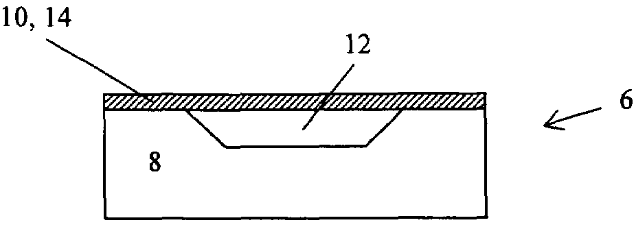
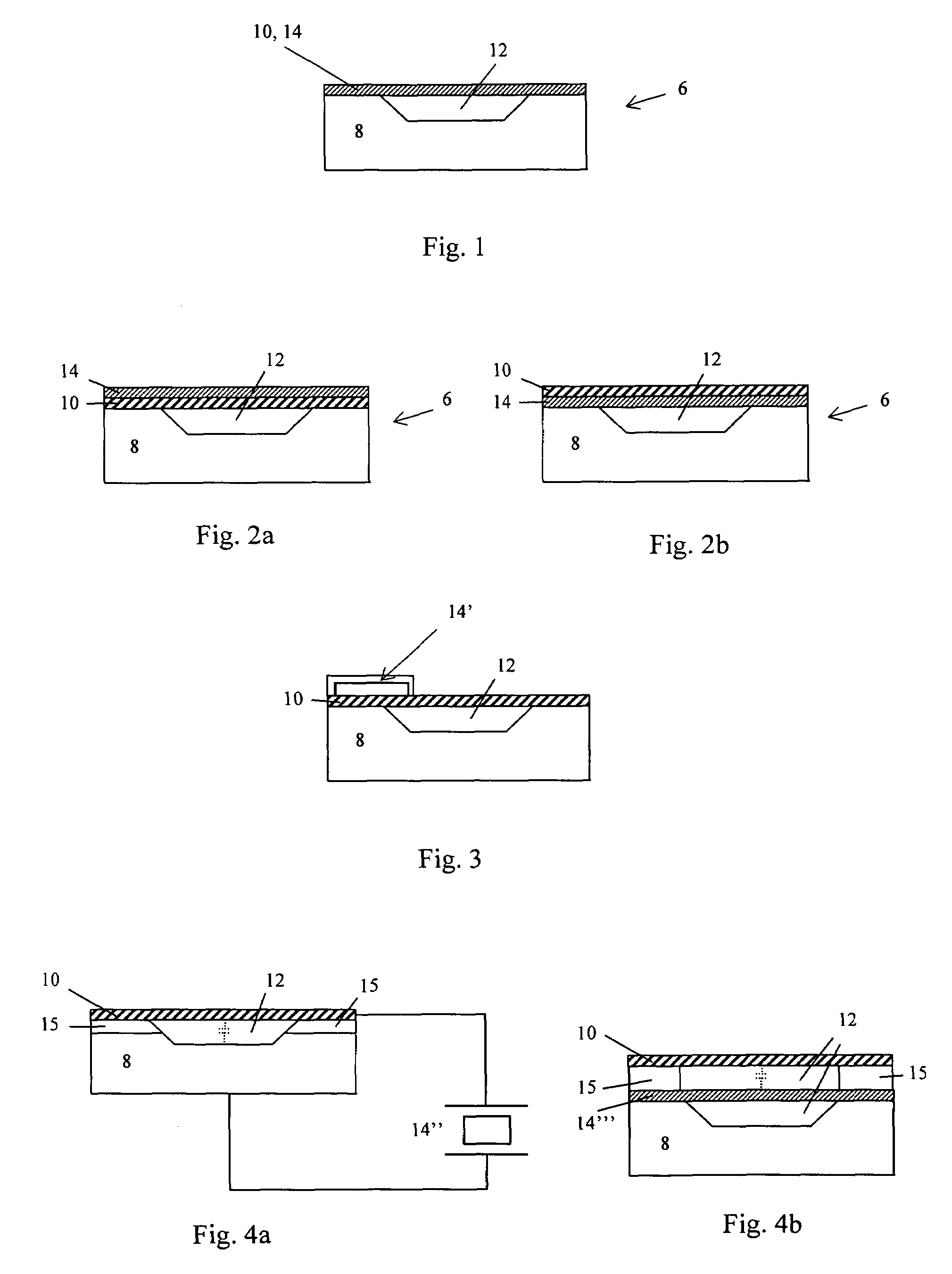
[0034]FIG. 1 is a schematic illustration showing a cross sectional view of a sensor chip 6 according to the present invention. The sensor chip 6 includes a substrate body 8 that comprises a recess covered by a pressure sensitive film 10 thereby forming a cavity 12.

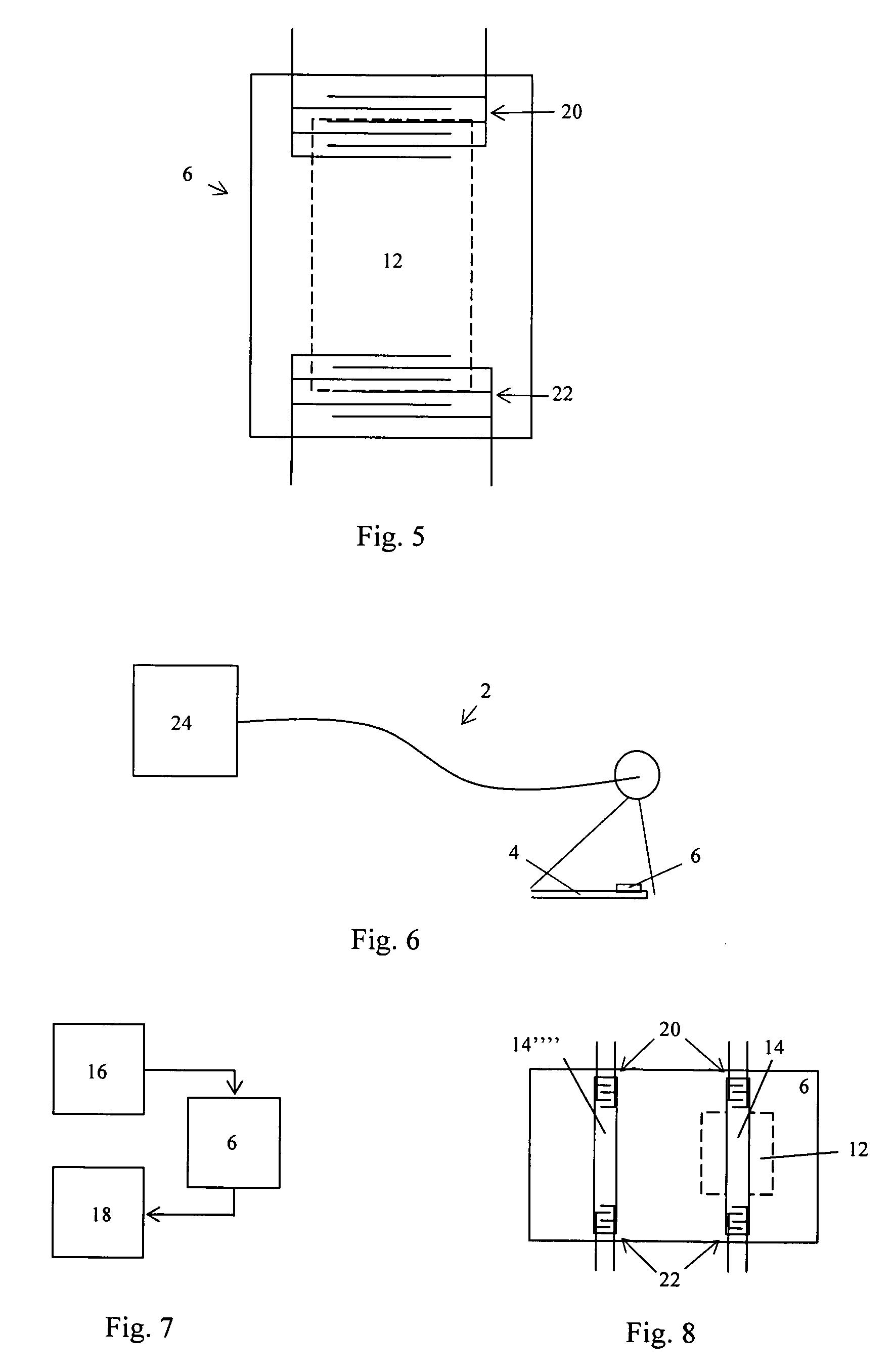
[0035]A piezoelectric element 14 is arranged in connection with the pressure sensitive film, and an energy feeding means 16 (see FIG. 7) is adapted to apply energy to the piezoelectric element such that acoustic waves are generated in the element. The piezoelectric element then generates an output signal, representing the pressure at the film, in dependence of measured properties of the acoustic waves related to the deflection of the pressure sensitive film.

[0036]In the first embodiment, illustrated in FIG. 1, the piezoelectric element is in the form of an elastic piezoelectric film being the pressure sensitive film.

second embodiment

[0037]FIG. 2a is a schematic illustration showing a cross sectional view of a sensor chip according to the present invention where the pressure sensitive film is attached to the substrate body and the piezoelectric film is attached on said pressure sensitive film.

third embodiment

[0038]FIG. 2b is a schematic illustration showing a cross sectional view of a sensor chip according to the present invention where the piezoelectric film is attached to the substrate body and the pressure sensitive film is attached on said piezoelectric film.

[0039]In the above first, second and third embodiments the energy is preferably applied to, and obtained from, the piezoelectric film via a pair of interdigital transducers (IDT) 20 and 22 (see FIG. 5), respectively. These are illustrated in FIG. 5 that is a schematic illustration of a top view of a sensor chip according to the present invention. The IDTs are either arranged on the side of the piezoelectric film facing the substrate body, or on the opposite side of the film. The inventor has found that by arranging the IDTs on the side of the piezoelectric film facing the substrate body advantageous impedance performance may be obtained.

[0040]As an alternative one of said IDTs is arranged on one side of the piezoelectric film an...


PUM

PropertyMeasurementUnit
thicknessaaaaaaaaaa
thicknessaaaaaaaaaa
thicknessaaaaaaaaaa

Abstract

A sensor and insertion assembly 2 is used for intravascular measurement of pressure in a living body. The assembly includes, a sensor chip 6 having a substrate body 8 with a recess covered by a pressure sensitive film 10 thereby forming a cavity 12. A piezoelectric element, preferably in the form of a piezoelectric film 14, is arranged in connection with the pressure sensitive film, and energy is applied to the piezoelectric element such that acoustic waves are generated in the element. The piezoelectric element is arranged to generate an output signal, representing the pressure at the film, in dependence on the measured properties of the acoustic waves related to the deflection of the pressure sensitive film.

Description

FIELD OF THE INVENTION[0001]The present invention relates generally to a pressure sensor, and in particular to sensor and insertion assemblies, in which a pressure sensor is mounted at the distal end, or close to the distal end, of an insertion means for intravascular measurements of pressure in a living body, and in particular to properties of the sensor element. A person skilled in the art realizes that the pressure sensor naturally may be arranged at any device adapted to be inserted into the body of a living body, e.g. a cannula, an electrode lead for heart stimulation, or a catheter.BACKGROUND OF THE INVENTION[0002]The need for measuring and recording physiological pressures, for example, in the coronary vessels, has triggered the development of miniaturized devices for enabling the access to the very narrow vessels, such as coronary vessels. Typically a sensor of very small size is mounted on a guide wire, which is inserted in e.g. the femoral artery and guided to the desired ...

Claims


Application Information

Patent Timeline
Patent Type & Authority Patents(United States)
IPC IPC(8): G01L7/00
CPCB60C23/0408G01L9/0025G01L9/008
Inventor SMITH, LEIFTULKKI, SAULI
Owner ST JUDE MEDICAL COORDINATION CENT
Why Eureka
Try Eureka