Device for carrying and fastening a robot

a technology for fastening devices and robots, applied in mechanical control devices, process and machine control, instruments, etc., can solve the problems of individual robots not being able to be set up in any desired arrangement, relatively expensive carrier devices, and steel material requirements, and achieve good vibration-damping properties

Inactive Publication Date: 2008-02-19
ROBERT BOSCH GMBH
View PDF14 Cites 9 Cited by
  • Summary
  • Abstract
  • Description
  • Claims
  • Application Information

AI Technical Summary

Benefits of technology

[0006]It is an object of the invention is to provide a device for carrying and fastening a robot, in particular a delta robot, this device being as space-saving as possible and nonetheless having good vibration-damping properties.

Problems solved by technology

A disadvantage, however, is that the carrier device takes up a relatively large amount of space, so that the individual robots cannot be set up in any desired arrangement.
Furthermore, these carrier devices are relatively expensive.
The reasons for this are the material requirements for steel, in particular high-grade steel, and the expensive manufacture, since the individual struts and supports have to be welded and / or screwed to one another.

Method used


Image

  • Device for carrying and fastening a robot
  • Device for carrying and fastening a robot
  • Device for carrying and fastening a robot

Examples


first embodiment

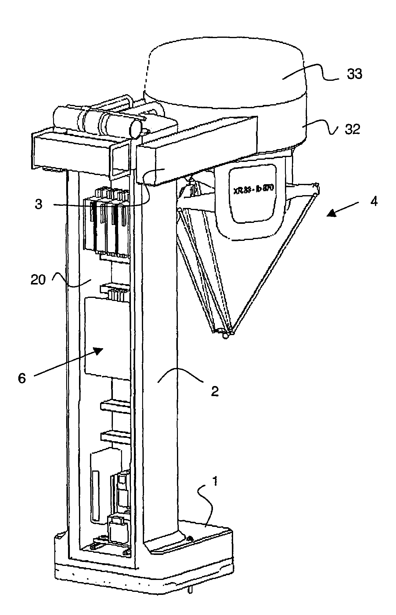
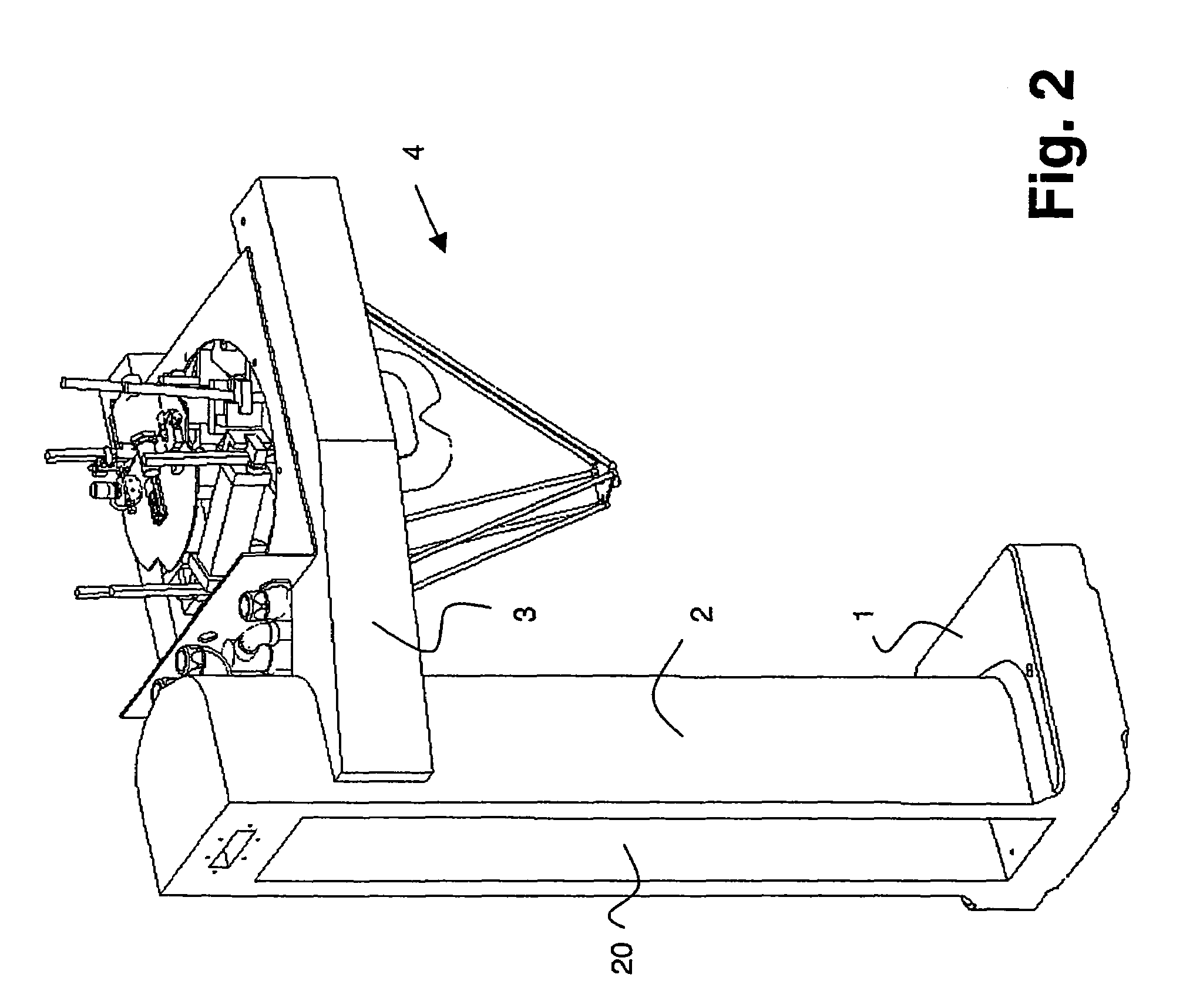
[0022]a device according to the invention is shown in FIG. 1. The device is designed in a gallows shape and has three components: a bottom horizontal component, a vertical component and a top essentially horizontal component. These components are formed in this sequence by a foot 1, a column 2 adjoining the foot 1 and at least one cantilever arm 3. The cantilever arm 3 preferably extends in an exactly horizontal direction. However, it is also possible for it not to form a right angle to the column 2. The foot 1 preferably extends in the same direction as the at least one cantilever arm 3, but is normally designed to be shorter. The foot 1 and / or the at least one cantilever arm preferably do not project on the opposite side of the column 2.

[0023]The foot 1 and column 2 are preferably made together in one piece, as shown here. However, they can also be composed of two or more parts. The at least one cantilever arm 3 is fastened to the column 2 in a fixed position. It is preferably fas...

third embodiment

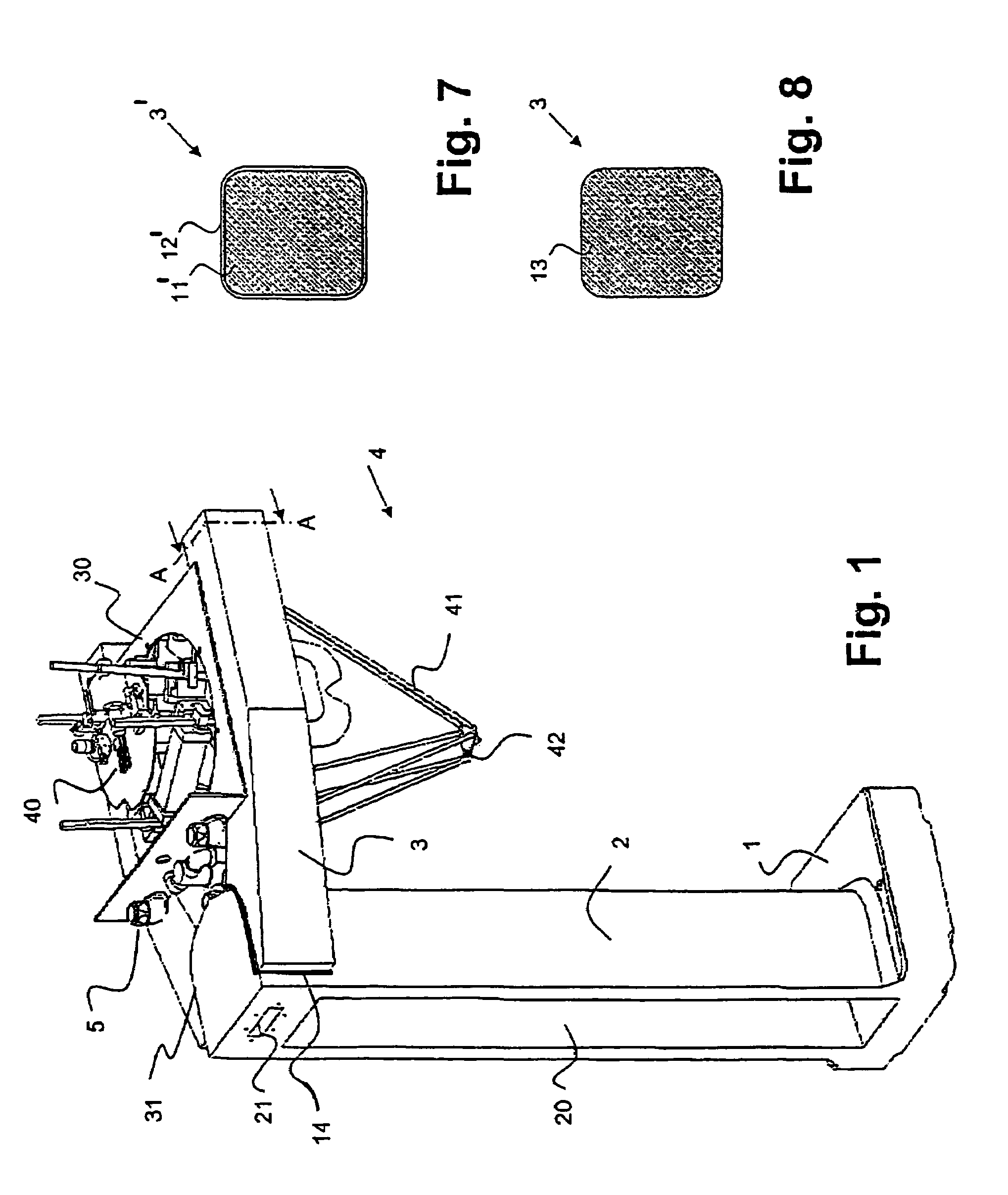
[0030]At least part of the device consists of a composite material. The column 2 and the foot 1 preferably consist entirely of a composite material. The cantilever arms 3, in a first variant (FIG. 8), are likewise produced entirely from a composite material and therefore form a solid body 13. In a second variant (FIG. 7), cantilever arms 3′ have a core 11′ consisting of a composite material and an outer envelope 12′ consisting of another material, in particular high-grade steel. In a third embodiment, cantilever arms are designed to be hollow on the inside, so that lines for the robot 4 can be passed through. In this case, the hollow body preferably consists of a composite material, in particular a cast mineral.

[0031]A suitable composite material is in particular a cast mineral. This composite material normally comprises essentially about 90-93% of minerals and stones and 7-10% of epoxy resin. Cast mineral is known in mechanical engineering. The preparation varies depending on the t...


PUM


Abstract

A device for carrying and fastening a robot (4), in particular a delta robot, is designed in a gallows shape. It has a foot (1), a column (2) adjoining the foot (1), and at least one cantilever arm (3), fastened to this column (2), for fastening the robot (4). The cantilever arm (3) in this case is fastened to the column (2) in a fixed position. The device consists at least partly of a composite material, in particular a cast mineral. This device for carrying and fastening a robot is extremely space-saving and nonetheless has good vibration-damping properties.

Description

TECHNICAL FIELD[0001]The invention relates to a device for carrying and fastening a robot. The device is suitable in particular for fastening robots which are movable in three-dimensional space, in particular delta robots.BACKGROUND OF THE INVENTION[0002]A robot, that is to say the actual actuating unit, must be fastened in a carrier device. This carrier device should be as robust as possible and have good vibration-damping properties. In addition, it is to allow as large a freedom of movement as possible for the robot.[0003]Robots which are movable in three-dimensional space are normally arranged in steel frames, what are referred to as cells. These frames comprise top and bottom horizontal components which are connected to one another via a vertical component. These frames are certainly robust. They can also be cleaned easily, which is an essential prerequisite in particular when the robot is used in the foodstuffs industry. A disadvantage, however, is that the carrier device take...

Claims


Application Information

Patent Timeline
Patent Type & Authority Patents(United States)
IPC IPC(8): B23Q1/01B25J19/00B23Q11/00B25J1/00B25J9/00B25J11/00B25J17/02
CPCB23Q1/015B23Q11/0032B25J17/0266B25J9/0051B25J9/0009Y10T74/20305B25J1/00
Inventor BURKERT, WOLFGANGLENHERR, HARALD
Owner ROBERT BOSCH GMBH
Why Eureka
Try Eureka