Powered hammer device

a hammer device and power technology, applied in the field of devices, can solve the problems of doubling the cost of demolition, causing the down time of the concrete breaker, and affecting the work efficiency so as to achieve the effect of reducing the wear of the hammer device, ensuring the smooth operation, and prolonging the working tim

Inactive Publication Date: 2008-02-19
TERMINATOR IP II
View PDF13 Cites 17 Cited by
  • Summary
  • Abstract
  • Description
  • Claims
  • Application Information

AI Technical Summary

Benefits of technology

[0094]A further advantage of the present invention is the ability of the drive system to change the speed of the rotation of the chain to allow the translation dog to engage the drive projection in the ideal position, or the ‘sweet spot’. Wear on the drop hammer device would be minimised and the smoothness of operation maximised, allowing an operator to handle longer working times with full concentration.
[0095]Furthermore, differing speeds of the hammer brought about by variation in the greasing of the hammer is minimised by inclusion of the spring. Variations in operation are also minimised, reducing wear and variation in responsiveness of the drop hammer device, allowing for a more consistent operation of the device.
[0096]According to another aspect of the present invention there is provided a hammer with at least two distal end conditions
[0098]the position of the end conditions can be reversed when required.
[0099]According to another aspect of the present invention there is provided a powered hammer device including a hammer configured with at least two end conditions
[0101]the position of the end conditions can be reversed when required.

Problems solved by technology

Concrete is a very brittle material and can therefore be smashed by impaction.
This double layer can therefore mean the need for more than one demolition machine on a job, doubling the cost of demolition and creating down time for the concrete breaker while the asphalt breaker works to expose the concrete.
Again, either further machines are required, or the industry is delayed over the winter months.
Furthermore, colder conditions increase the likelihood of damage to the machinery due to temperature gradients forming across the hammer leading to thermal shock and resultant fracture.
The breaking up of ground that is frozen due to permafrost with current technology has proved to be virtually impossible and as such construction is limited to the warmer months that in some cases can be as short as ten to twelve weeks.
It would be a limitation to produce a system that could be varied, but required high maintenance or a large period of downtime to implement.

Method used


Image

  • Powered hammer device
  • Powered hammer device
  • Powered hammer device

Examples


Embodiment Construction

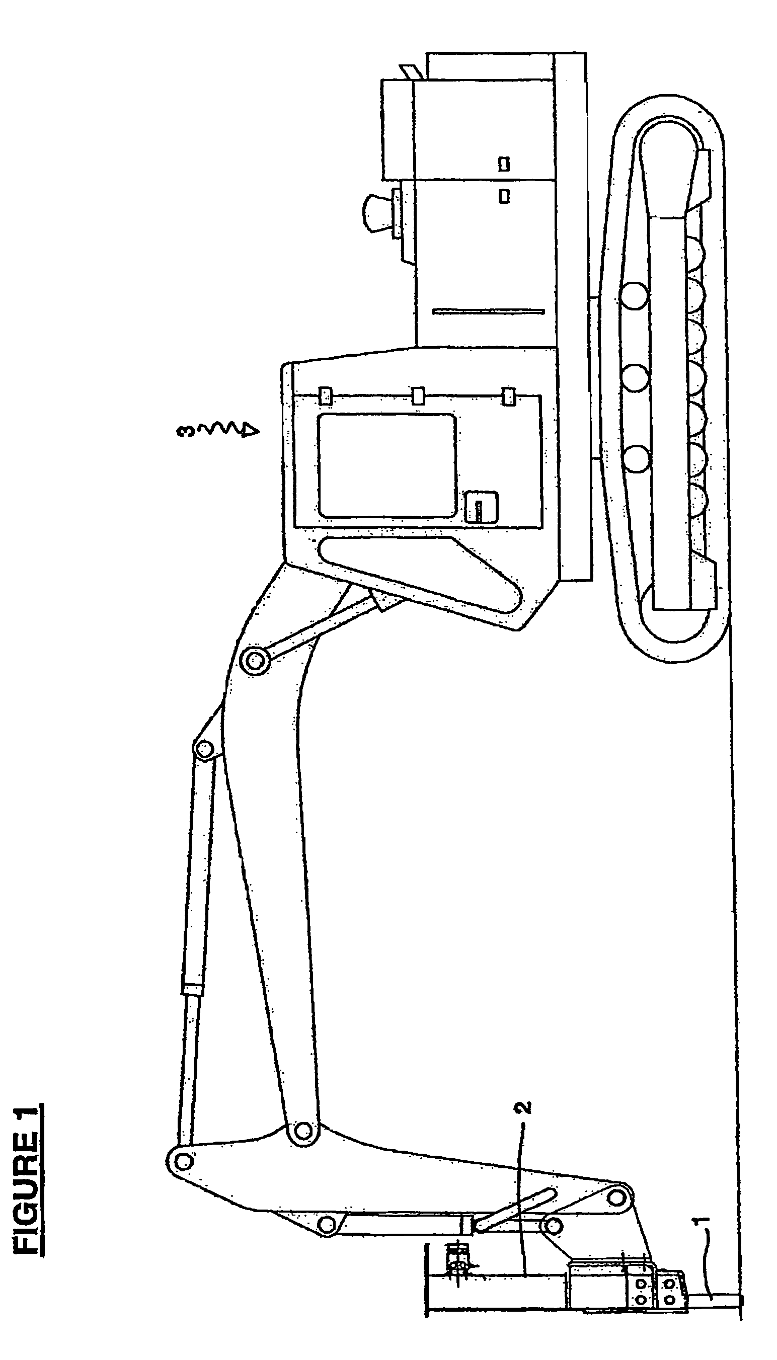
[0144]With reference to FIG. 1, there is illustrated a powered hammer (1), encased within a hammer housing (2) which is attached to a hydraulic excavator generally indicated by arrow 3.

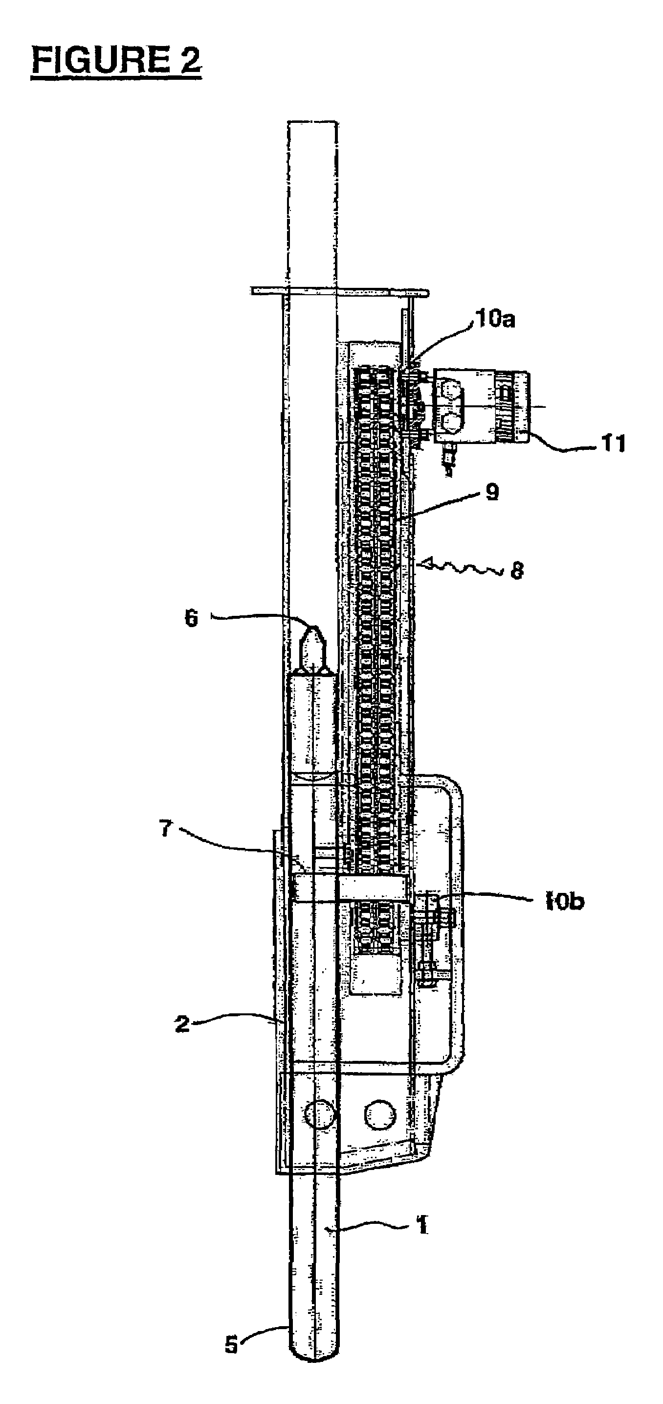
[0145]With respect to FIG. 2 there is shown a close-up of a powered hammer device generally indicated by arrow 4. The hammer device (4) consists of a hammer (1) with a dull end (5) and a sharp end (6), a first projection (7), a drive mechanism generally indicated by arrow 8, the drive mechanism in the form of a rotating chain (9), with two cogs (10a and b), a hydraulic activating means (11) and a hammer housing (2).

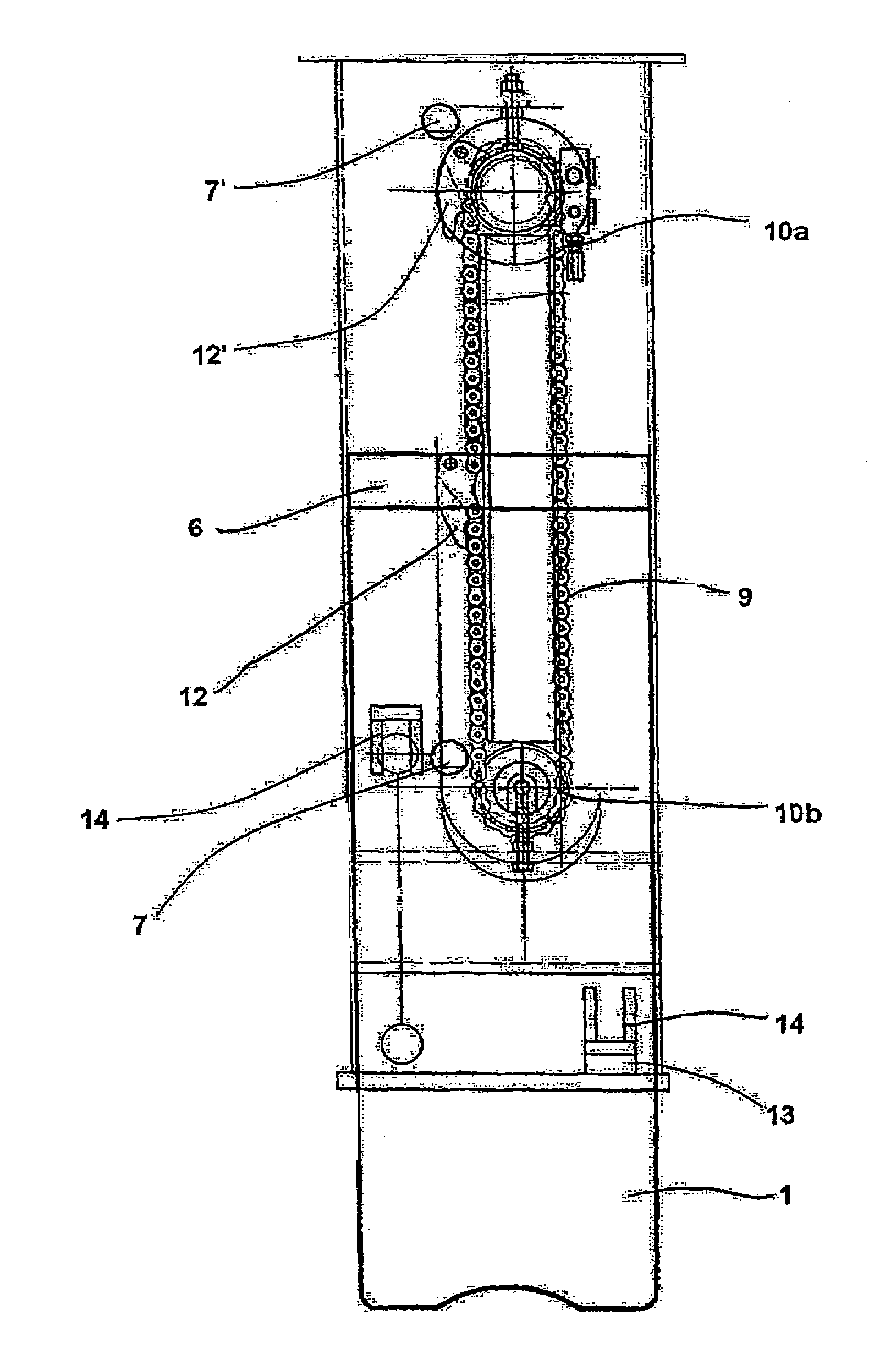
[0146]With respect to FIG. 3 there is shown a side view of the hammer (1) with the rotating chain (9) (partially removed for clarity), an upper first sprockets (10a) and a lower second sprocket (10b) which the chain (9) rotates around, a translation dog (12), a first projection (7) and a second projection (14) on the hammer (1).

[0147]FIG. 3 shows the hammer (1) in a resting position in whic...


PUM

PropertyMeasurementUnit
angleaaaaaaaaaa
speedaaaaaaaaaa
anglesaaaaaaaaaa

Abstract

The present invention relates to a powered hammer device including: a hammer with at least a first and a second projection; at least one translation dog adapted to engage with said projections, and a drive mechanism capable of moving the translation dog substantially reciprocally between a first and a second opposed directions, characterised in that the translation dog is adapted to engage with the first projection to move the hammer in the first direction, the translation dog then engaging the second projection to move the hammer in the reciprocal second direction.

Description

CROSS-REFERENCE TO OTHER APPLICATIONS[0001]This is a continuation-in-part of International Application No. PCT / NZ2003 / 000237, filed on Oct. 21, 2003, which claims priority from New Zealand Patent Application No. 522158, filed on Oct. 21, 2002, and New Zealand Patent Application No. 526516, filed on Jun. 13, 2003.TECHNICAL FIELD[0002]This invention relates to an improved device. In particular it relates to an improvement to a device that is used for the breaking or weakening of material.BACKGROUND ART[0003]It is common practice in the construction or demolition industry to use hydraulic hammers in order to break up concrete, rock, hard ground, asphalt or unwanted structures for removal or further construction.[0004]A large proportion of the material to be broken up consists of either concrete or asphalt. These materials have very different characteristic and therefore require different type of machinery or tool bits to break them up. Concrete is a very brittle material and can theref...

Claims


Application Information

Patent Timeline
Patent Type & Authority Patents(United States)
IPC IPC(8): E02D7/06B28D1/26E02D7/08E02D7/16E02D13/00
CPCB28D1/26E02D7/16E02D7/08
Inventor ROBSON, ANGUS PETER
Owner TERMINATOR IP II
Why Eureka
Try Eureka