Apparatus for use with coiled barrier material

a technology of coiled barriers and apparatus, which is applied in the direction of load securing, lifting devices, transportation items, etc., can solve the problem of requiring a dedicated road-going vehicle, and achieve the effect of facilitating sliding

Active Publication Date: 2008-02-19
COCHRANE STEEL PRODS
View PDF10 Cites 10 Cited by
  • Summary
  • Abstract
  • Description
  • Claims
  • Application Information

AI Technical Summary

Benefits of technology

[0006]Preferably, in the storage position, the boom extension piece hangs downwardly from the free end of the boom arrangement and acts to retain the at least one coil of barrier material, in a compressed state, on the boom arrangement. The boom extension piece may include an outer end, an inner end which is adjacent the free end of the boom arrangement and which, as noted, is preferably pivotally attached to the boom arrangement, and a region, between the outer end and the inner end, which is higher than the outer end and the inner when the boom extension piece is in the operative position. A smooth transition may be provided between the boom arrangement and the boom extension piece to facilitate sliding of the at least one coil of barrier material along the length of the boom arrangement and the boom extension piece.

Problems solved by technology

This type of arrangement works satisfactorily but it requires a dedicated road-going vehicle.

Method used


Image

  • Apparatus for use with coiled barrier material
  • Apparatus for use with coiled barrier material
  • Apparatus for use with coiled barrier material

Examples


Embodiment Construction

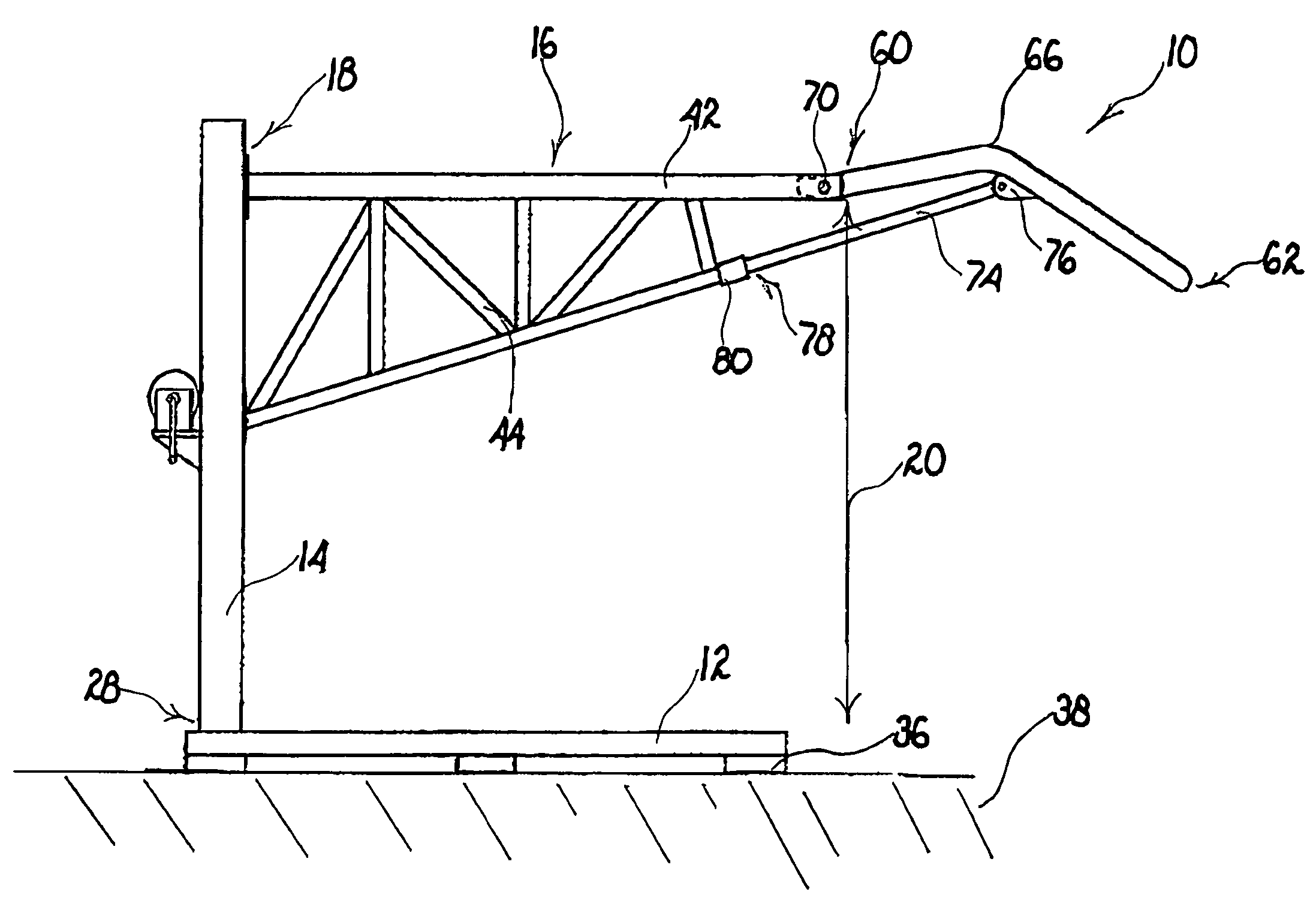
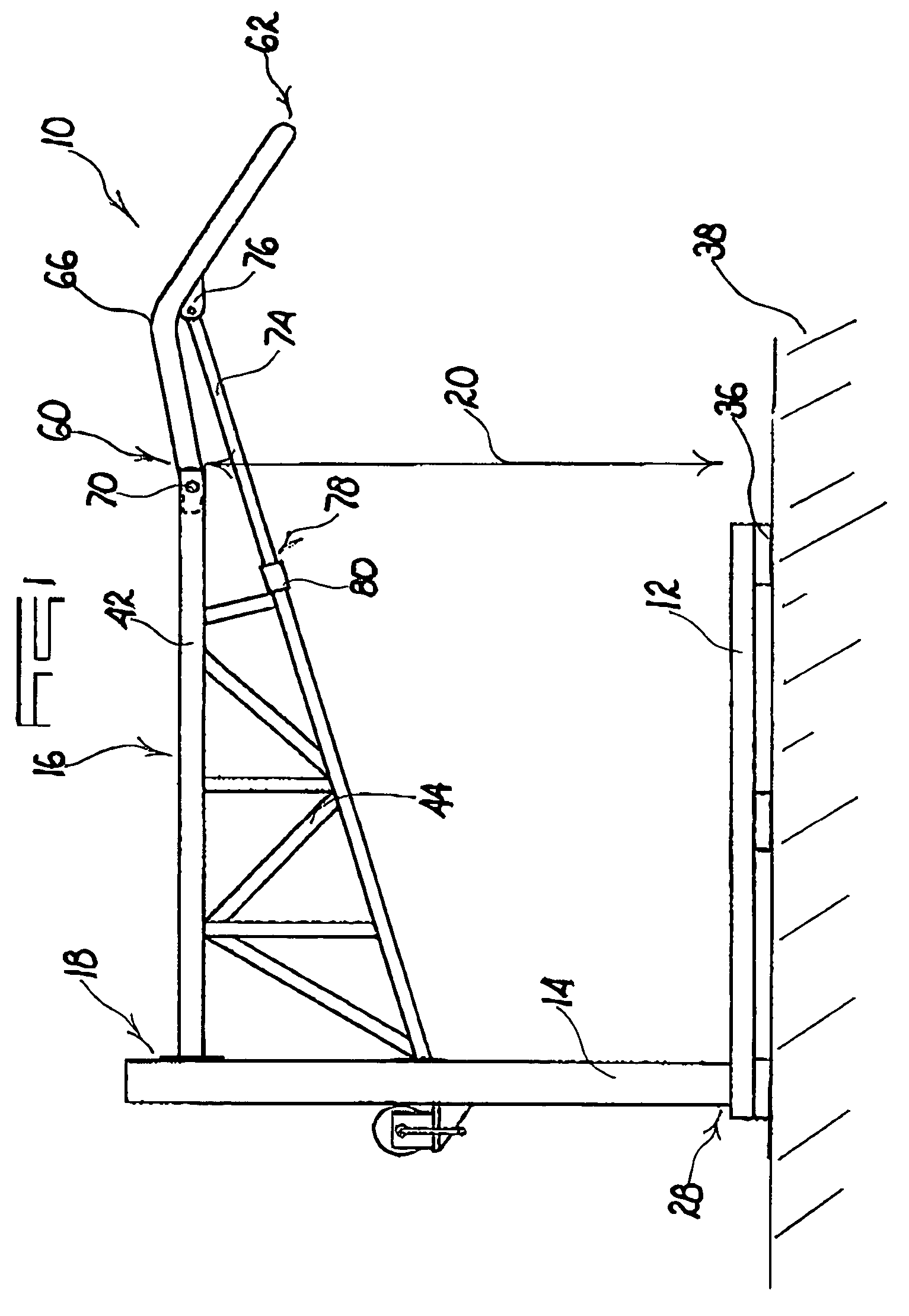
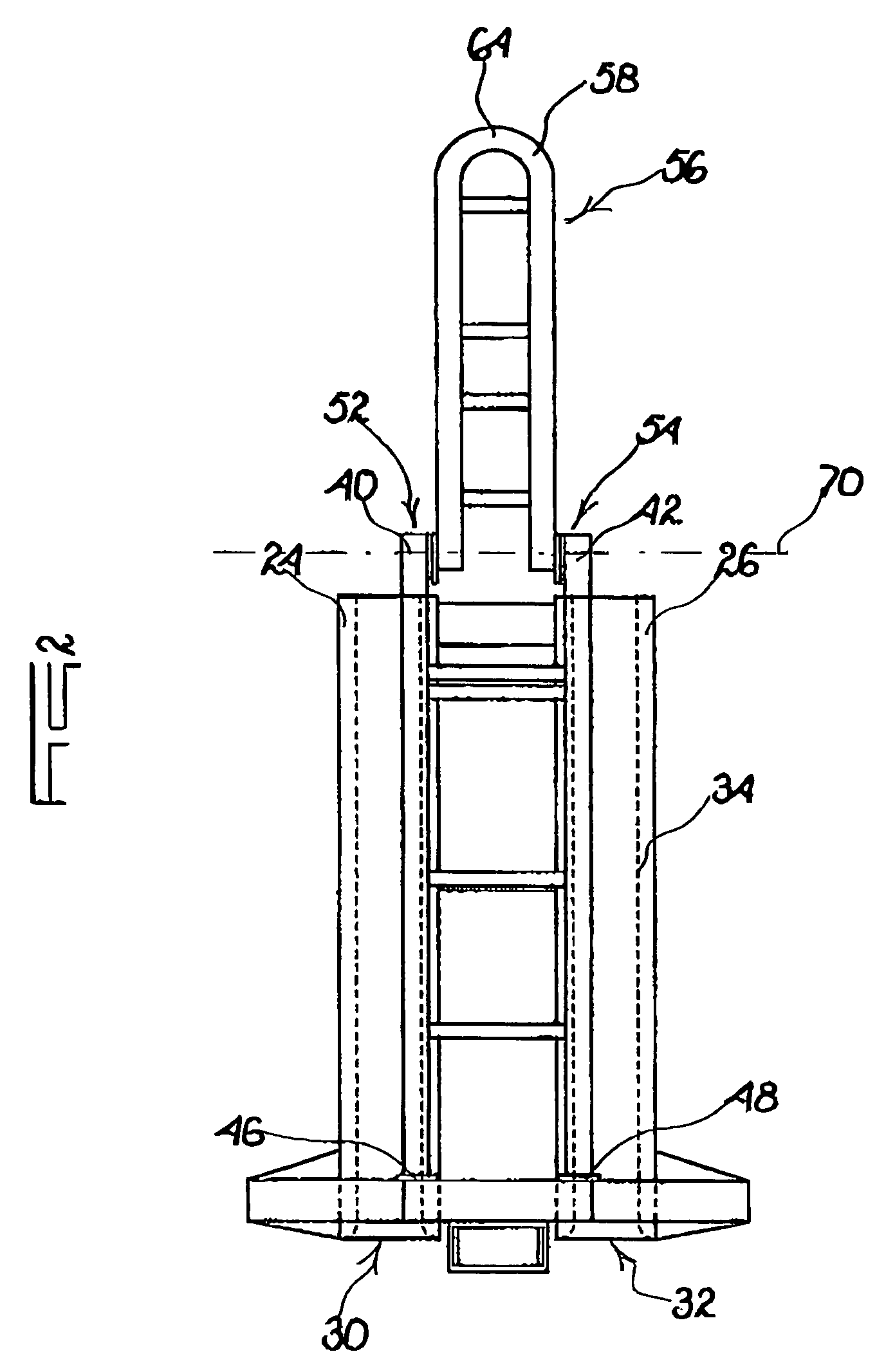
[0020]FIGS. 1 to 3 of the accompanying drawings illustrate apparatus 10 according to the invention in an operative mode from the side, in plan and from one end respectively.

[0021]The apparatus 10 includes a ground-engaging structure 12, a pedestal-like support 14 which extends upwardly from one end of the structure 12, and a boom arrangement 16 which is attached at a first end 18 to the support, near an upper end thereof, and which extends in cantilever fashion over the ground-engaging structure 12 being spaced therefrom by a distance 20.

[0022]The ground-engaging structure 12 includes two elongate beams 24 and 26 respectively which are spaced apart and which are substantially parallel to each other. At ends which are adjacent a base 28 of the support 14 the beams form respective recesses 30 and 32 into which tines of a forklift device not shown, are respectively insertable. Each beam 24 may be formed from tubular material or from a channel-type structure with in-turned downwardly fa...


PUM


Abstract

Apparatus for dispensing coiled barb tape which includes a frame in which is located a boom from which the coiled barb tape is suspended. The boom is extensible to assist in deployment of the barb tape and the frame, apart from protecting the coiled barb tape, provides a stacking characteristic with similar frames.

Description

BACKGROUND OF THE INVENTION[0001]This invention relates generally to the deployment or recovery of coiled barrier material formed with a plurality of windings. The barrier material may comprise barb tape, barb wire or any similar deterrent material.[0002]The specification of U.S. Pat. No. 4,744,708 describes a barrier which can be deployed from a load bed of a trailer or other vehicle and which includes a number of stacked coils in a pyramid-like structure with an uppermost coil engaged with a rigid boom cantilevered above the load bed. This type of arrangement works satisfactorily but it requires a dedicated road-going vehicle.[0003]A need exists for an alternative mechanism which can be used with coiled barrier material and which does not necessarily require a dedicated vehicle. It is also desirable to be able to provide a measure of protection for the barrier material so that, at least during transport or storage, the barrier material is less likely to be damaged.SUMMARY OF INVEN...

Claims


Application Information

Patent Timeline
Patent Type & Authority Patents(United States)
IPC IPC(8): B21F25/00B66D1/00B61D3/16F41H11/08
CPCF41H11/08B65G2201/0232
Inventor COCHRANE, RICHARD BRUCE
Owner COCHRANE STEEL PRODS
Why Eureka
Try Eureka