Parallel robot

a robot and parallel technology, applied in the field of parallel robots, can solve the problem achieve the effect of large workspace-to-footprint ratio, small floor space, and small footprin

Active Publication Date: 2008-02-19
MERZ PHARMA GMBH & CO KGAA +1
View PDF14 Cites 51 Cited by
  • Summary
  • Abstract
  • Description
  • Claims
  • Application Information

AI Technical Summary

Benefits of technology

[0020]Another object of the invention is to provide a parallel robot with a large workspace-to-footprint ratio and similar characteristics across the workspace. According to an embodiment, a main arm and two supporting arms for influencing the position and orientation of an object are advantageously arranged to rotate about a common central axis, thereby allowing the object to be positioned and oriented in a large cylindrical workspace with an angular range of 360° or more. The workspace characteristics remain the same in the angular direction of the cylindrical workspace, and similar in the axial direction. The arms are mounted to a base, which requires very little floor space due to the coaxial arrangement of the main arm and the two support arms. This results in a large workspace-to-footprint ratio, which compares to that of SCARA robots and thereby exceeds that of most commonly known parallel robots, particularly the ones suspended from trusses. In another embodiment of the invention, the main arm and the two support arms rotate about separate parallel axes, which can further simplify the design of the mechanism.
[0021]Another object of the invention is to provide a parallel robot that can achieve high end-effector accelerations and speeds. According to an embodiment of this invention, small rotations of the actuated arms of a robot are translated into large displacements of the end component and the supported object. Moreover, the actuators of the robot, e.g. rotary motors, are mounted onto or close to the base, which reduces the moving mass of the mechanism and allows for the selection of powerful and potentially heavier actuators, without having the negative effect on the dynamics as seen in serial robots. Moreover, a robot mechanism according to this invention comprises a main arm and two support arms with respective forearms. The forearms of the two support arms experience only pulling or compression forces, allowing the use of light, simple, and cheap materials such as carbon fiber tubes. This further reduces the moving mass of the mechanism. The forearm of the main arm experiences pulling or compression forces, as well as some bending during lateral motions. In an embodiment, the bending load is significantly reduced by a guiding linkage interposed between the main arm and the two support arms. The guiding linkage keeps the main arm at equal angles to the two support arms.
[0022]It is a further object of the invention to provide a robot with improved structural stiffness and accuracy. Mechanisms according to this invention comprise a parallel structure of multiple arms for supporting an end component, the arms thereby sharing the loads on the end component. This type of arm arrangement gives mechanisms of this invention truss-like behavior and a high structural stiffness. Since the forearms are mostly subjected to compression or pulling forces, mechanisms with a design according to the invention can be built in a light and cost-efficient manner and with a high stiffness-to-mass ratio, particularly in comparison to serial devices. In addition, the parallel arrangement of the arms compensates for positioning errors of the individual actuators and leads to a high positioning accuracy. According to an embodiment of this invention, a mechanism has a low number of joints of the revolute type only, the joints being made of standard ball bearings for example. In high-precision applications, such a design is not only more cost-efficient, but also more accurate compared to robots, which employ ball-joints to connect their actuated arms to the end-effector.
[0023]A further object of this invention is to provide a mechanism that allows for a modular, scalable design and simple, robust cable management. In an embodiment, a mechanism having a design according to the invention allows for extremely simple cable management by integration of most actuators into the stationary base. Other actuators are mounted on the moving structure, but close to the base. Therefore, most cables and other utility lines do not need to move or bend during operation of the robot. This improves the operational reliability particularly compared to traditional serial robots. Moreover, actuators integrated into or close to base combined with a light and inexpensive forearm structure greatly enhance the scalability of mechanisms provided by this invention. Varying the output parameters such as workspace size only requires substitution of the inexpensive forearm structure while costly actuators and base structures can be reused. This allows for a reconfigurable standard design that can be used in many applications with minimum modifications. Moreover, the support arms of mechanisms according to this invention have a similar design, allowing the reuse of components and therefore lower manufacturing and maintenance cost.
[0024]Another object of the invention is to provide a parallel robot comprising less links compared to other robots of its kind. According to an embodiment of this invention, a robot mechanism includes a main arm and two support arms for positioning and orienting an object in space with at least three degrees of freedom. The main arm includes a forearm and a belt arrangement to retain the inclination of the object, while the support arms include two forearms. Thus, a robot according to this invention can be built with only three forearms or links. In another embodiment, the belt arrangement of the main arm is replaced by a further link, resulting in a total of four links that support the object in space. The lower number of links translates into less material and manufacturing cost, less joints, and therefore more accuracy, less weight, less space requirements of the arm structure of the mechanism, and a lower risk of interferences with objects in proximity to the robot.

Problems solved by technology

This results in a large workspace-to-footprint ratio, which compares to that of SCARA robots and thereby exceeds that of most commonly known parallel robots, particularly the ones suspended from trusses.

Method used


Image

  • Parallel robot
  • Parallel robot
  • Parallel robot

Examples


Embodiment Construction

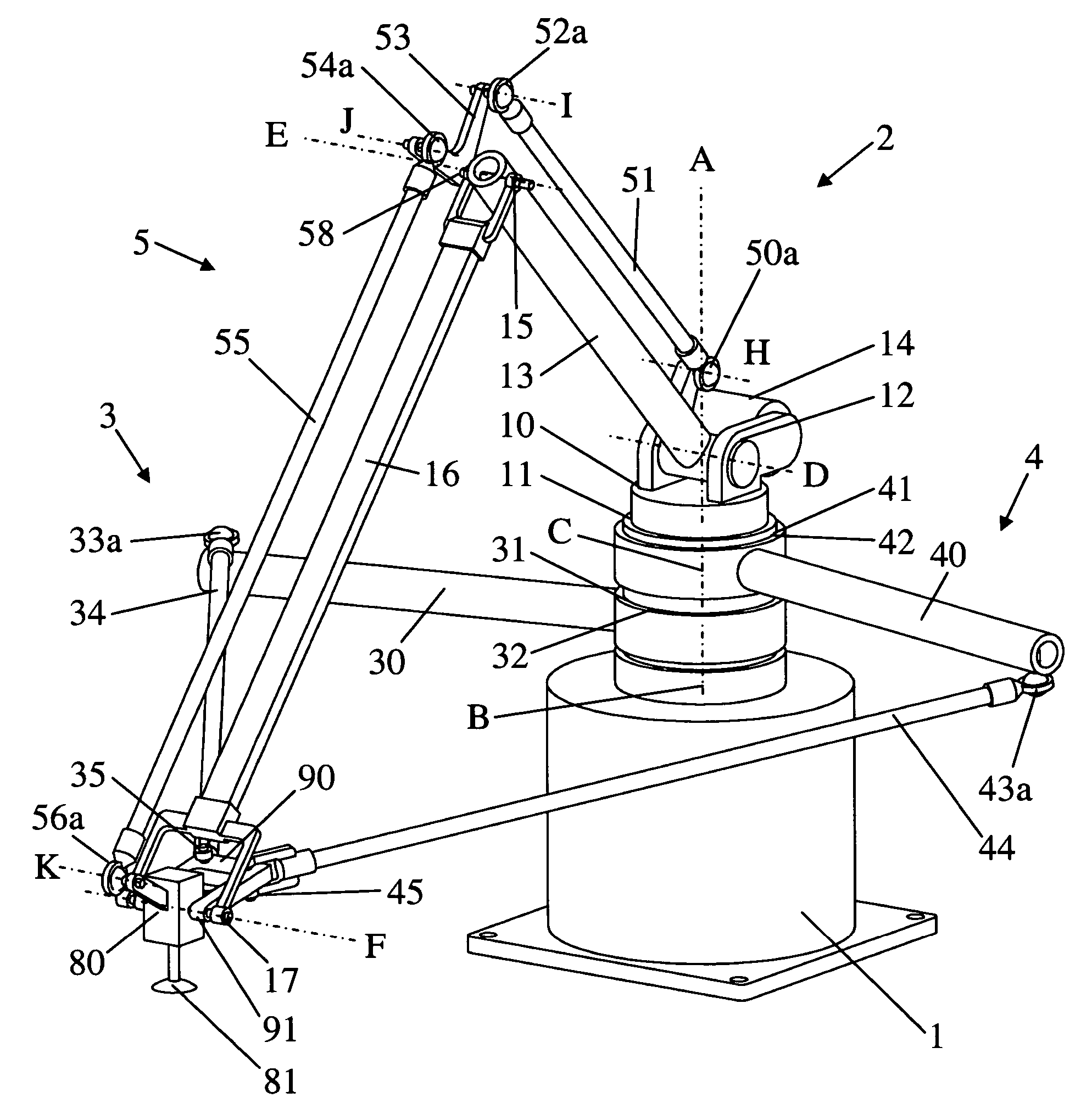
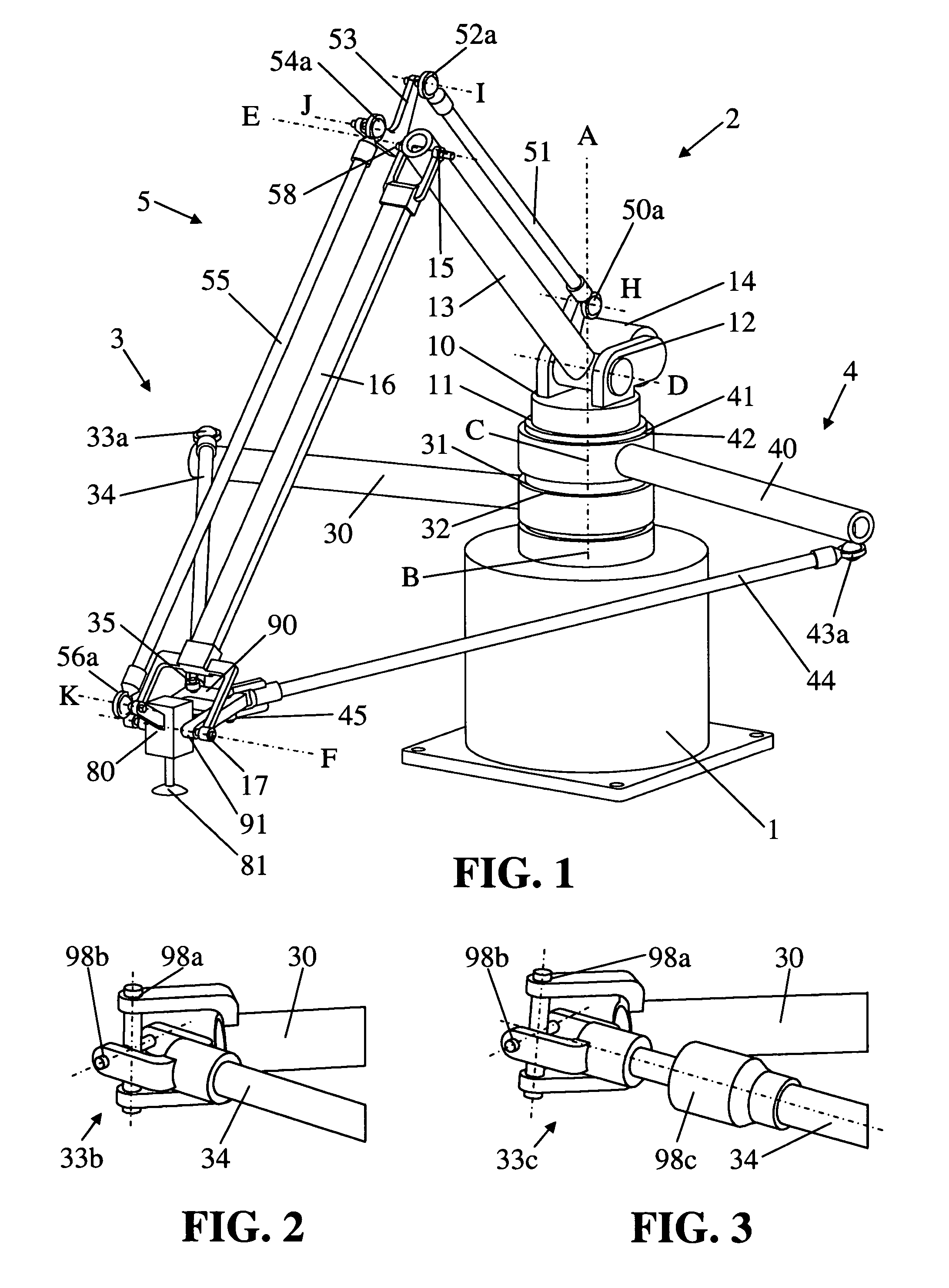
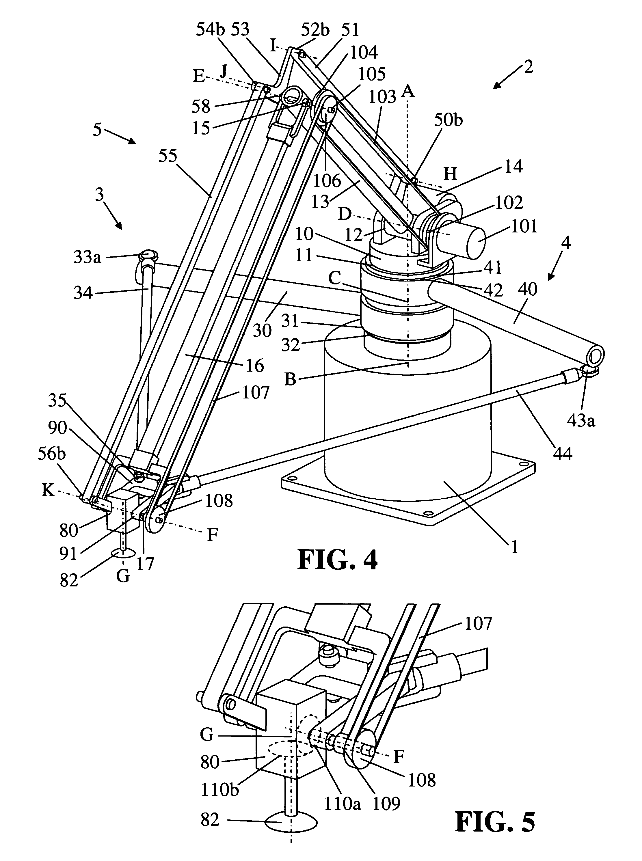
[0051]Now referring to the drawings, wherein like numerals designate like components, FIG. 1 shows a parallel robot or parallel kinematics mechanism, hence referred to by mechanism, constructed in accordance with teachings of the present invention. The mechanism includes a fixed base and is operable to position and orient an object in a cylindrical workspace with three degrees of freedom and retained inclination with respect to the base. A main arm and two supporting arms together determine the position and orientation of the object, while the main arm also retains the inclination of the object, as will be described.

[0052]As illustrated in FIG. 1, the mechanism comprises a base 1, a main arm 2, and a first and second support arm 3 and 4 interposed between the base 1 and the main arm 2. The main arm 2 includes a platform 10, an end component 80 for directly or indirectly supporting an object, and linkage means 5 interposed between the platform 10 and the end component 80. The main ar...


PUM


Abstract

A parallel robot or parallel kinematics mechanism is provided for uses such as robotics or machining. The mechanism comprises a fixed base, a main arm, and a first and second support arm to position and orient an object in a cylindrical space with at least three degrees of freedom and retained inclination. The main arm includes an end component for supporting the object and linkage means to retain the inclination of the end component with respect to the base for all positions and orientations of the end component. The mechanism advantageously provides a large cylindrical workspace and a small footprint and is capable of moving an object at high accelerations and speeds. The mechanism can be equipped with an additional motor to orient an object, thereby providing the mobility of a SCARA robot. Alternatively, it can be equipped with passive transmission means that allow for an object to be displaced in parallel to itself.

Description

BACKGROUND[0001]The present invention generally relates to an apparatus with multiple actuated arms arranged in parallel for positioning and orienting an object in space with at least three degrees of freedom and retained inclination.[0002]A need exists for simple and effective parallel robots, also known as parallel kinematics mechanisms. In general, robots are used in applications such as handling, assembling, positioning, picking and placing, packaging, palletizing, measuring, machining, and so on. Robots can be classified as serial or parallel. Serial robots, or serial kinematics mechanisms, are widely used and presently dominate the market.[0003]A serial robot has a series of cantilever beams that are movably connected together in an end-to-end fashion by actuated prismatic or revolute joints, forming an open loop. When a serial robot is subjected to loading, the position of the farthest member, i.e., the end-effector, is subject to the cumulative deflections of all serial memb...

Claims


Application Information

Patent Timeline
Patent Type & Authority Patents(United States)
IPC IPC(8): B25J18/00
CPCB25J9/104B25J17/0266B25J19/0016Y10T74/20329Y10S414/115Y10T74/20305
Inventor MERZROY, SHAMBHU NATH
Owner MERZ PHARMA GMBH & CO KGAA
Why Eureka
Try Eureka