Fixture

a technology of fixing and fixing brackets, applied in the field of fixing brackets, can solve the problems of forming space or clearing between the fixing bracket and the bone material, unsuitable for both the stability of the anchorage and the healing process, and achieve the effect of reducing the resistance of the fixing bracket, ensuring the anchorage, and optimum adaptation to the contour of the surrounding tissue material

Inactive Publication Date: 2008-02-19
PIOS BIOTECH
View PDF13 Cites 18 Cited by
  • Summary
  • Abstract
  • Description
  • Claims
  • Application Information

AI Technical Summary

Benefits of technology

[0008]Because the application portion includes a part that widens in the aforesaid manner, the fixture will essentially fill out the space that would otherwise arise. Moreover, as a result of the elastic resilience said flared part will adapt to the shape corresponded by the widening occurring at the outer end of the hole when anchoring the fixture. This eliminates the danger of healing problems caused by the presence of said space. Moreover, said part will be compressed and deformed as a result of the widening at the mouth of the hole. Said part is therewith tightened against the flared surface and thus locked. This is achieved because the stresses generated tend to force said part to return to its original shape. The resilient part thus creates its own seating against the surrounding tissue, resulting in a highly stable anchorage.
[0009]According to one preferred embodiment of the invention, the flared part is formed by an outer wall that surrounds a cavity which is open towards the outer end of the application portion and which is provided with through-penetrating slots that extend from the outer end of the application portion, such as to connect the cavity with the outside of the outer wall. As a result of the slots, said outer wall forms a number of tongue-like flaps whose free ends are able to spring inwards at the outer end of the application portion. The elastic resilience is therewith achieved in a constructively simple manner, wherewith the resilient part is well able to adapt to the shape of the widening at the mouth of the insertion hole.
[0011]Screwing of the anchoring portion into bone tissue is the most usual method of securing the fixture. Consequently, the inventive fixture is of significant interest since it is of the kind that can be screwed into bone tissue. Moreover, the inventive design of the application portion is particularly purposeful when anchoring the fixture by screwing the same into bone tissue. Screwing of the fixture into bone tissue is also facilitated by the fact that the flared part, is rotationally symmetrical.
[0017]Because the edge that leads when screwing in the fixture is blunt, there is less risk of said edge hooking fast into surrounding tissue material when screwing in the fixture. This means that the compressive deformation taking place when screwing in the fixture will not be disturbed by said edge hooking into surrounding tissue material. The danger that hooking of the leading edge into surrounding tissue will create a resistance to screwing-in the fixture is similarly reduced. The cone can be considered as being “stroked smoothly” by the surrounding tissue material when screwing in the fixture. On the other hand, the obliqueness of the cone has the reverse effect when unscrewing the fixture, since the slots then hamper unscrewing of the fixture. This reduces the danger of the fixture being unscrewed unintentionally, therewith making the anchorage more secure.
[0018]According to another preferred embodiment of the invention, the slots have an angle of 20°-40° at their axially and radially outer ends. This angle will preferably lie in the range of 27°-33°, where an angle of about 30° is the most suitable in many applications. An angle in the aforesaid range will cause the desired deformation to be as uniform and as harmonious as possible, and allow optimum adaptation to the contour of the surrounding tissue material to be achieved.

Problems solved by technology

This results in the formation of a space or clearing between the fixture and the bone material.
This is unsuitable both with respect to the stability of the anchorage and the healing process.

Method used


Image

  • Fixture
  • Fixture
  • Fixture

Examples


Embodiment Construction

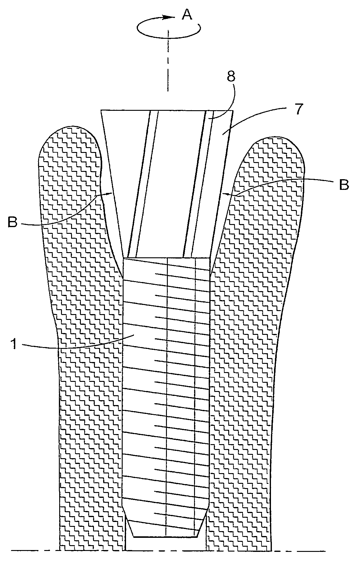
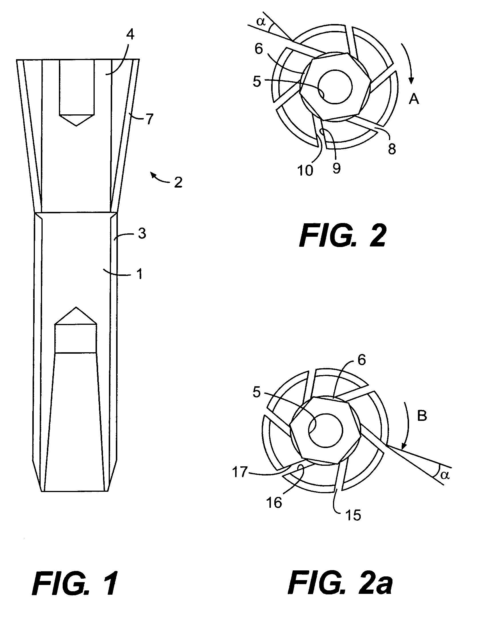
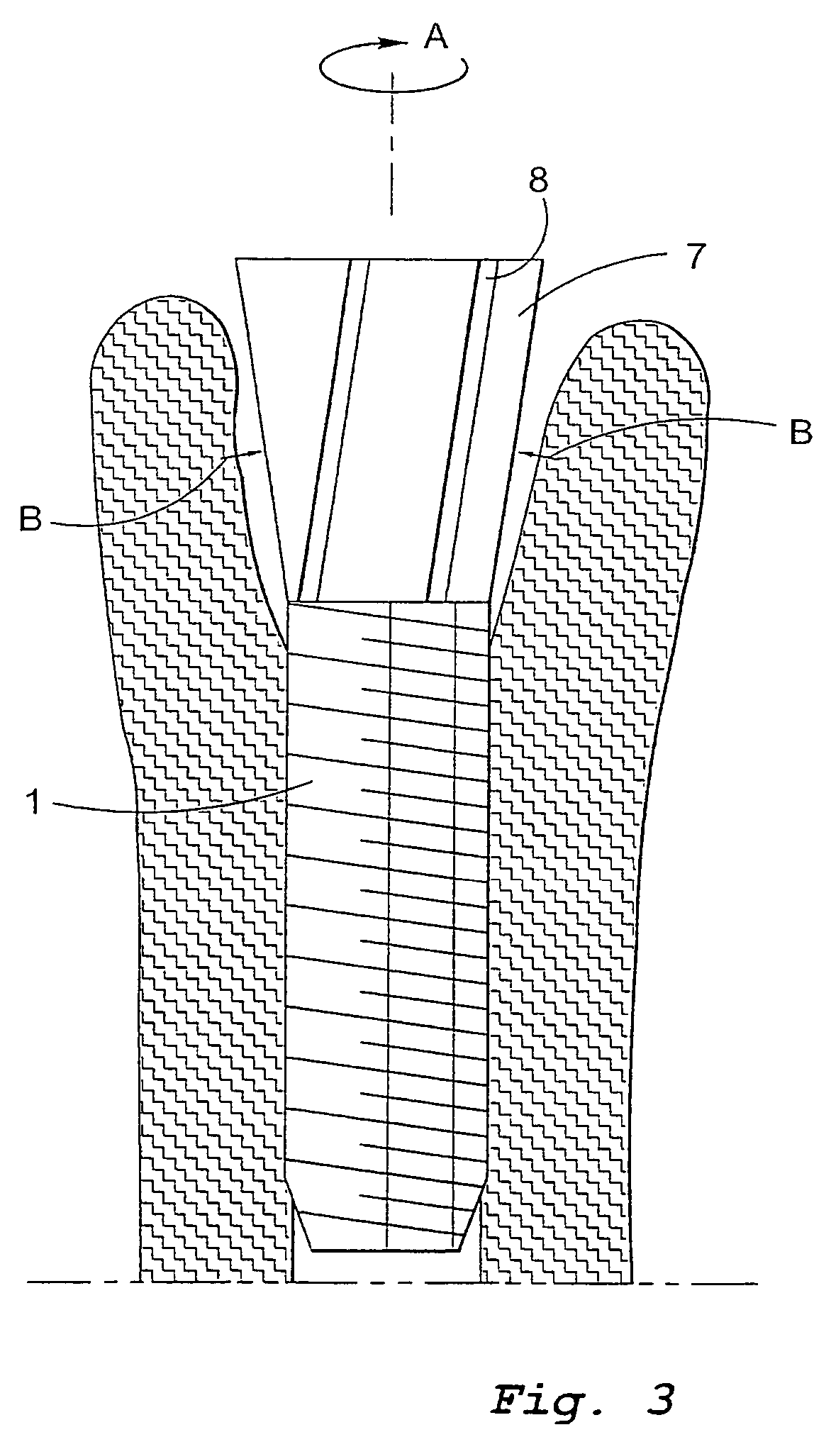
[0028]FIG. 1 is a longitudinal sectional view of an inventive fixture. The illustrated fixture is intended for a finger joint and is dimensioned to this end. The fixture comprises an anchoring portion 1 and an application portion 2. The anchoring portion has a length of about 20 mm and the application portion a length of about 10 mm.

[0029]The anchoring portion includes an external screw thread 3 which is adapted to enable the fixture to be screwed into a hole predrilled in bone tissue. In the illustrated case, the thread is an M6 thread. The predrilled hole will preferably have a diameter that is slightly smaller than the inner diameter of the thread, i.e. a diameter of about 4.5 mm. The thread 3 extends along the full length of the anchoring portion 1.

[0030]Because the present invention is directed particularly to the design of the application portion 2, a detailed description of the design of the anchoring portion is believed to be unnecessary.

[0031]The application portion is comp...


PUM


Abstract

A fixture having an anchoring portion and an application portion intended for connection to a prosthesis. The application portion has an outer end and an end connected to the anchoring portion. The application portion includes a flared part whose outer dimensions widen from the end of that part connected to the anchoring portion in a direction toward the outer end of the application portion. This flared part is elastically resilient transversely to the longitudinal direction of the fixture.

Description

FIELD OF INVENTION[0001]The present invention relates to a so-called fixture which is anchored to bone tissue. The fixture is of a kind that includes an anchoring portion with which the fixture is anchored, and an application portion intended for connection with a prosthesis and having an outer end and an end which is connected with the anchoring portion.BACKGROUND OF THE INVENTION[0002]Fixtures of this kind are used in prosthesis surgery, wherein the prosthesis, parts of a prosthesis, or a prosthesis holder is / are anchored in the bone tissue of a person with the aid of one or more such fixtures. The fixtures may be used for different types of prosthesis and are of different sizes, said size depending on the type of prosthesis concerned. However, the fixtures according to the present invention are primarily intended for anchorage in tubular bone and may be used, for instance, in the reconstruction of joints, such as finger joints and hip joints. However, the invention is not restric...

Claims


Application Information

Patent Timeline
Patent Type & Authority Patents(United States)
IPC IPC(8): A61B17/58A61B17/86A61B17/88A61C8/00A61F2/00A61F2/30A61F2/36A61F2/42
CPCA61C8/0033A61C8/0089A61F2/30721A61F2/30749A61F2/4241A61B17/8625A61B17/863A61F2002/30143A61F2002/3021A61F2002/30224A61F2002/30598A61F2002/30795A61F2002/30848A61F2002/3085A61F2002/30863A61F2230/0017A61F2230/0067A61F2230/0069A61F2310/00023Y10S606/907A61F2002/30594A61F2002/30845A61C8/00
Inventor BRANEMARK, PER-INGVAR
Owner PIOS BIOTECH
Why Eureka
Try Eureka