Semiconductor power device with charge compensation structure and monolithic integrated circuit, and method for fabricating it
a technology of monolithic integrated circuits and power devices, applied in the direction of semiconductor devices, electrical devices, transistors, etc., to achieve the effect of improving the isolation of potentials
- Summary
- Abstract
- Description
- Claims
- Application Information
AI Technical Summary
Benefits of technology
Problems solved by technology
Method used
Image
Examples
first embodiment
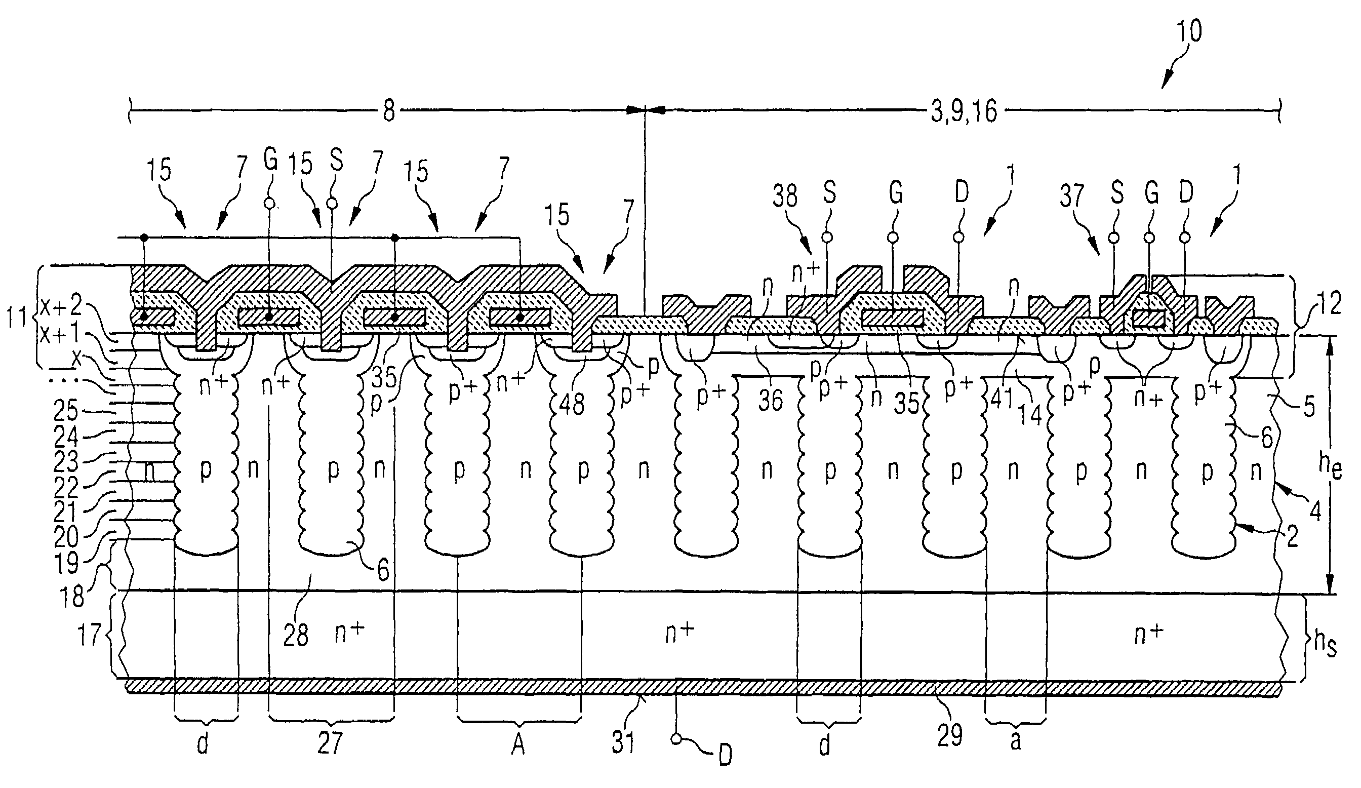
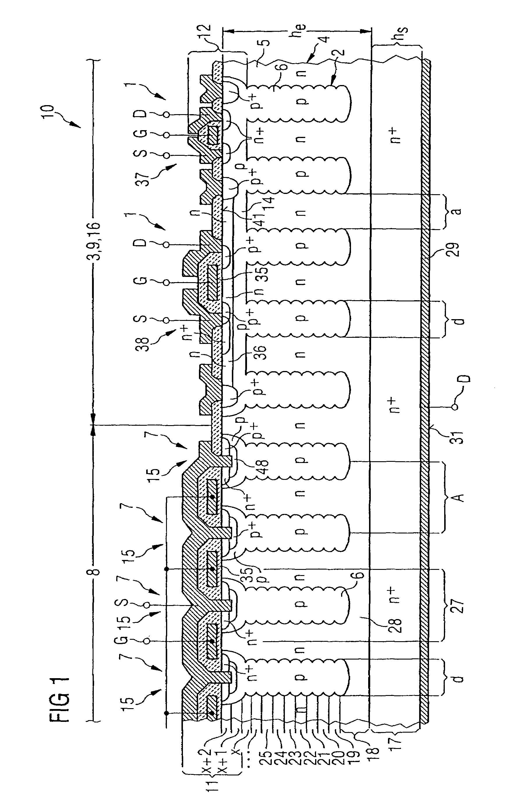
[0072]FIG. 1 shows a diagrammatic cross section through a semiconductor chip 4 of a semiconductor power device 10 of the invention. The semiconductor power device 10 has a charge compensation structure 2. In the semiconductor chip volume 5 above said power compensation structure 2 there are arranged both a region 8 with semiconductor power elements 7 that form a vertical MOS transistor 15 and a region 9 having semiconductor circuit elements 1 of a monolithic integrated circuit 3. In this case, complimentarily doped pillars 6 made of p−-conducting monocrystalline material extend in the vertical direction right into surface regions 11 of the semiconductor power components 7.
[0073]The charge compensation structure 2 with its charge compensation cells 27 and the p−-conducting pillars 6 does not project into a surface region 12 for the semiconductor circuit elements 1, but rather touches, with the topmost pillar region, a p−-conducting well 14 that extends over the entire region 9 of the...
second embodiment
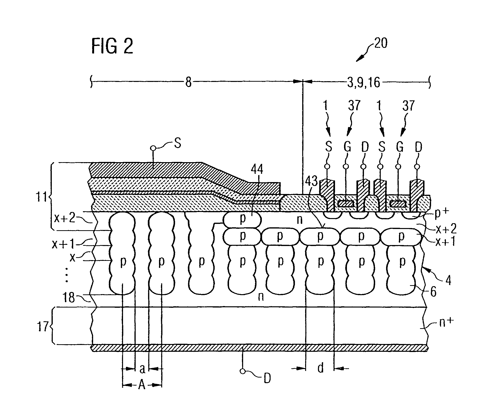
[0079]FIG. 2 shows a diagrammatic cross section through a semiconductor chip 4 of a semiconductor power device 20 of the invention. This cross-sectional view only shows a detail exhibiting the formation of an n-conducting well 36 for a monolithic integrated circuit with p-channel MOS field-effect transistors 38. A schematic sketch of this type for two MOS transistors 37 of this type with source S, gate G and drain D electrodes can be seen at the top right edge of the illustration. The n-conducting well 36 is delimited by a semiconductor structure comprising p-conducting pillars 6, the x+1 epitaxial layer having widened p-conducting zones that are patterned in such a way that the upper regions 42 of the p-conducting pillars 6 of the charge compensation structure 2 touch one another and thus form a closed underside 43 for the n-conducting well 36, while laterally the topmost layer 44 of the p-conducting pillars 6 is likewise widened in such a way as to form a closed edge all around th...
fourth embodiment
[0082]FIG. 4 shows a diagrammatic cross section through a semiconductor chip 4 of a semiconductor power device 40 of the invention. Components with functions identical to those of the previous figures are identified by the same reference symbols and are not discussed in any greater detail. In this case, headless p-conducting pillars 33 are provided in the corridor region 13, the diameter d′ of said pillars being greater than the diameter d of pillar structures that reach as far as the top side of the semiconductor chip in the corridor region B. A charge compensation cell 27 is arranged in the left-hand edge region of the cross section of FIG. 4, the p-conducting pillar 6 of said charge compensation cell having the same diameter d′ as the headless p-conducting pillars 33 in the corridor region 13.
[0083]FIG. 5 shows a diagrammatic plan view of an active top side of a semiconductor chip 4 in accordance with FIG. 4 with a detail from a corridor 13. A plurality of p-conducting pillars 6 ...
PUM
 Abstract
Description
Claims
Application Information
 - R&D
- Intellectual Property
- Life Sciences
- Materials
- Tech Scout
- Unparalleled Data Quality
- Higher Quality Content
- 60% Fewer Hallucinations
Browse by: Latest US Patents, China's latest patents, Technical Efficacy Thesaurus, Application Domain, Technology Topic, Popular Technical Reports.
© 2025 PatSnap. All rights reserved.Legal|Privacy policy|Modern Slavery Act Transparency Statement|Sitemap|About US| Contact US: help@patsnap.com


