
System and method for spatially diverse radar signal processing

a spatially diverse and radar signal technology, applied in the field of radar signal processing, can solve the problems of preventing unlimited integration, limiting the stability of electronics, and presenting a further limit on the possible integration time for object detection, so as to enhance the object signal to noise

Active Publication Date: 2008-02-19
HUMATICS CORP
View PDF14 Cites 28 Cited by
  • Summary
  • Abstract
  • Description
  • Claims
  • Application Information

AI Technical Summary

Benefits of technology

This approach improves the detection range and accuracy of moving objects by enhancing signal-to-noise and signal-to-clutter ratios, enabling effective detection even when objects move significantly during integration time.

Problems solved by technology

In practice, however, there are limitations in the stability of the electronics and in the time allowed to achieve a result that prevent unlimited integration.
For moving objects, the motion of the object presents a further limit on the possible integration time for object detection.
If the object moves more than the range equivalent of the resolution bandwidth or more than the length of the object during the integration time, the object may move entirely out of the response bin, resulting in integration of noise alone, without an object response signal, reducing rather than increasing system sensitivity.
This technique can improve object detection in stationary clutter, but does not improve the object signal to noise ratio without clutter and is of limited utility against moving clutter.
However, because it is not feasible to sharpen the beam significantly by modifying the electromagnetics of the antenna system because of its small size, there is a need for improved techniques for the removal of clutter in radar return signals transmitted and received by a radar on a moving platform.

Method used


Image

  • System and method for spatially diverse radar signal processing
  • System and method for spatially diverse radar signal processing
  • System and method for spatially diverse radar signal processing

Examples


Embodiment Construction

[0049]The present invention will now be described more fully in detail with reference to the accompanying drawings, in which the preferred embodiments of the invention are shown. This invention should not, however, be construed as limited to the embodiments set forth herein; rather, they are provided so that this disclosure will be thorough and complete and will fully convey the scope of the invention to those skilled in art. Like numbers refer to like elements throughout.

UWB Background

[0050]Impulse radio has been described in a series of patents, including U.S. Pat. Nos. 4,641,317 (issued Feb. 3, 1987), 4,743,906 (issued May 10, 1988), 4,813,057 (issued Mar. 14, 1989), 4,979,186 (issued Dec. 18, 1990), and 5,363,108 (issued Nov. 8, 1994) to Larry W. Fullerton. A second generation of impulse radio patents includes U.S. Pat. Nos. 5,677,927 (issued Oct. 14, 1997), 5,687,169 (issued Nov. 11, 1997), 5,764,696 (issued Jun. 9, 1998), 5,832,035 (issued Nov. 3, 1998), and 5,969,663 (issued ...


PUM


Abstract

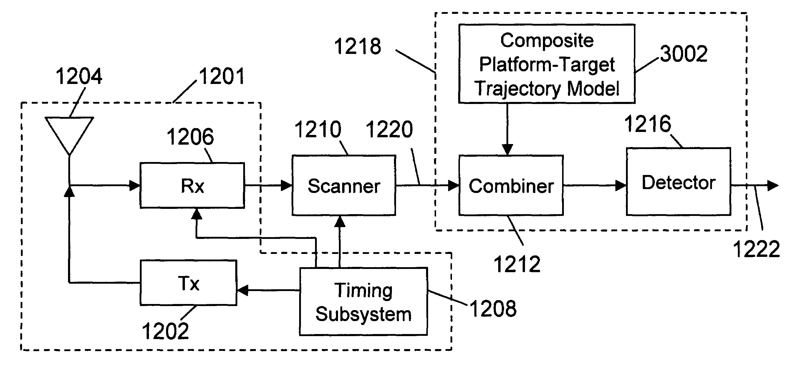
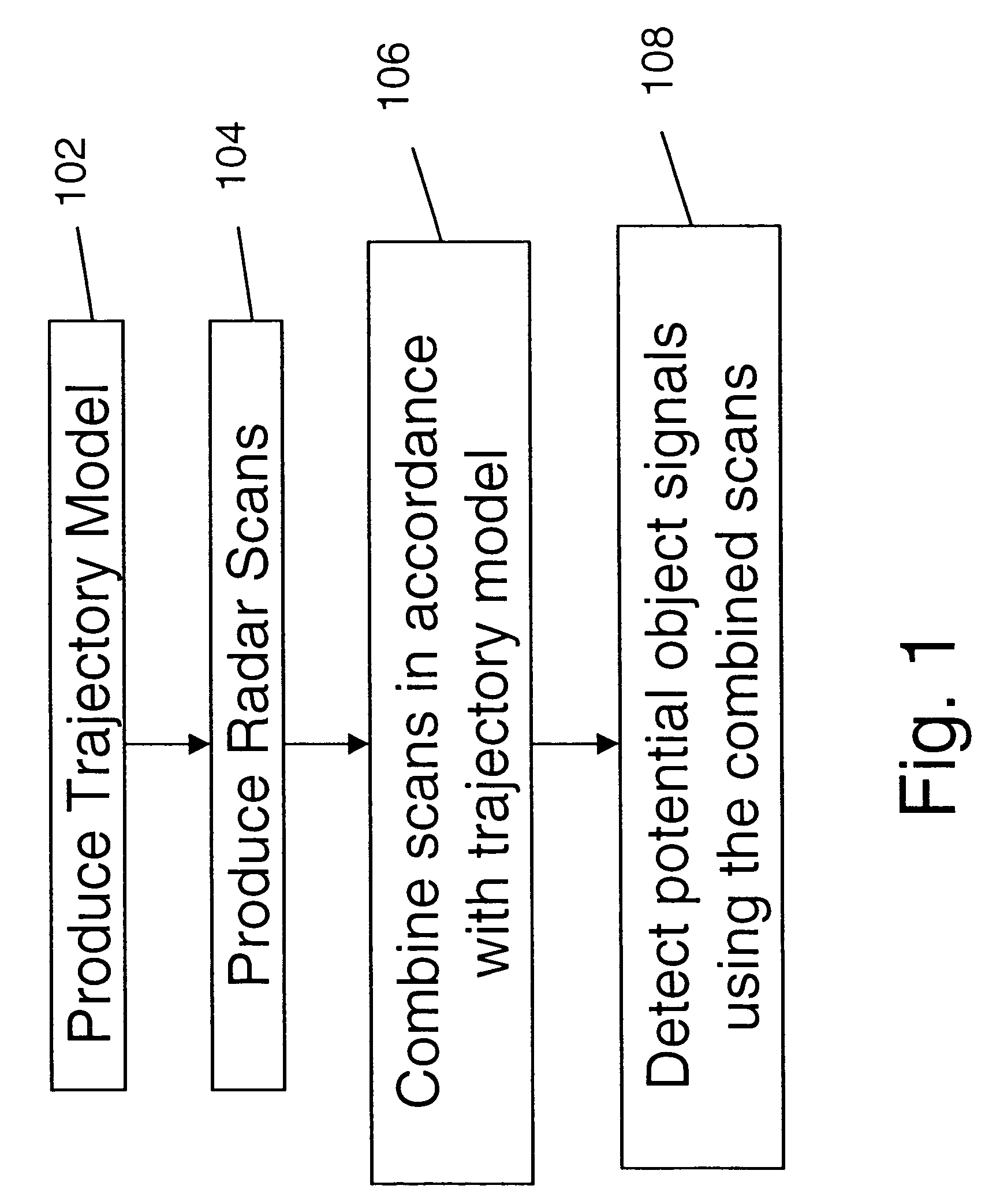
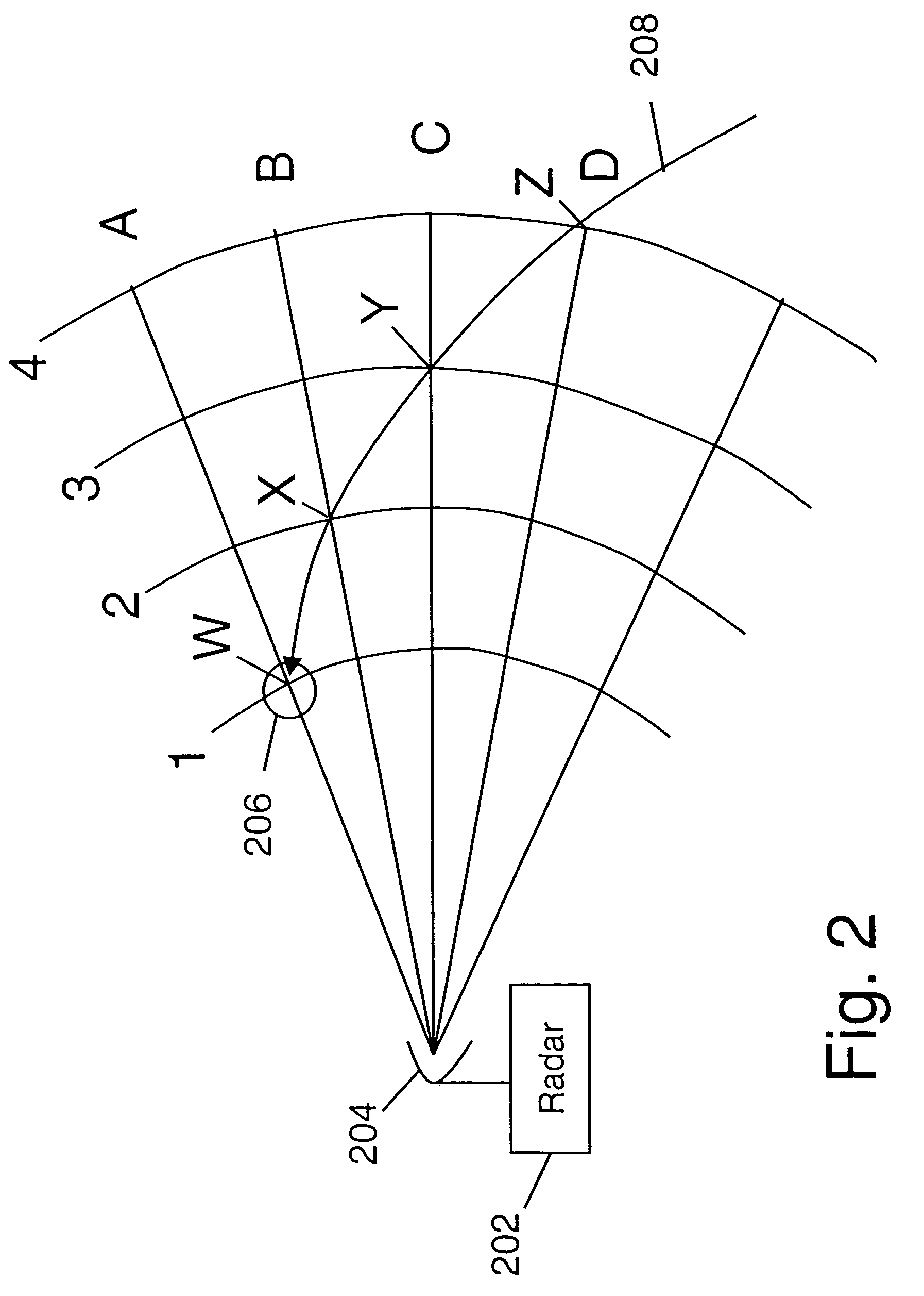
An ultra wideband radar system for detecting objects where at least one of the radar system or the object is moving. The radar may be scanned in at least one dimension, which may include angle or range. The system includes a scan combiner that combines scan information in accordance with a trajectory characteristic of a moving object and / or of a moving platform on which the radar resides. Scans may be combined by integration or filtering. A fast calculation method is described wherein the scans are combined into subsets and subsets are shifted in accordance with the trajectory characteristics before further combination. The scan information is combined in accordance with trajectory characteristics to enhance the object signal to noise. Further features are described wherein the scan information is combined according to a family of candidate trajectories and / or object positions.

Description

CROSS REFERENCE TO RELATED APPLICATIONS[0001]This application is a continuation-in-part application of U.S. patent application Ser. No. 10 / 856,037, titled “Apparatus and Method for Detecting Moving Objects”, filed May 28, 2004 by Fullerton et al. now U.S. Pat. No. 7,132,975. This application also claims priority to provisional U.S. patent application No. 60 / 621,166, titled “Spatially Diverse Radar Clutter Filtering”, filed Oct. 22, 2004 by Fullerton, both applications are hereby incorporated herein by reference in their entirety.BACKGROUND[0002]1. Field of the Invention[0003]The present invention pertains generally to the field of radar signal processing and more particularly to the processing of radar signals for detection of an object where at least one of the radar or object are moving.[0004]2. Background of the Invention[0005]Radar systems, including ultra wideband (UWB) radar systems are often employed to detect moving objects. The moving objects of interest vary from system to...

Claims


Application Information

Patent Timeline
Patent Type & Authority Patents(United States)
IPC IPC(8): G01S13/62
CPCG01S13/72
Inventor FULLERTON, LARRY W.RICHARDS, JAMES
Owner HUMATICS CORP
Learn More