Vertical field neurovascular array coil

a neurovascular array and vertical field technology, applied in the field of magnetic resonance imaging, can solve the problems of inefficiency of co-planar surface array coils for vertical field systems, various modifications to co-planar designs have been proposed with limited success,

Active Publication Date: 2008-02-19
GENERAL ELECTRIC CO
View PDF7 Cites 20 Cited by
  • Summary
  • Abstract
  • Description
  • Claims
  • Application Information

AI Technical Summary

Problems solved by technology

However, such co-planar surface array coils are, in general, inefficient for a vertical field system because the condition required for maximal signal detection can hardly be fulfilled.
Various modifications to the co-planar designs have been proposed with limited success.

Method used


Image

  • Vertical field neurovascular array coil
  • Vertical field neurovascular array coil
  • Vertical field neurovascular array coil

Examples


Embodiment Construction

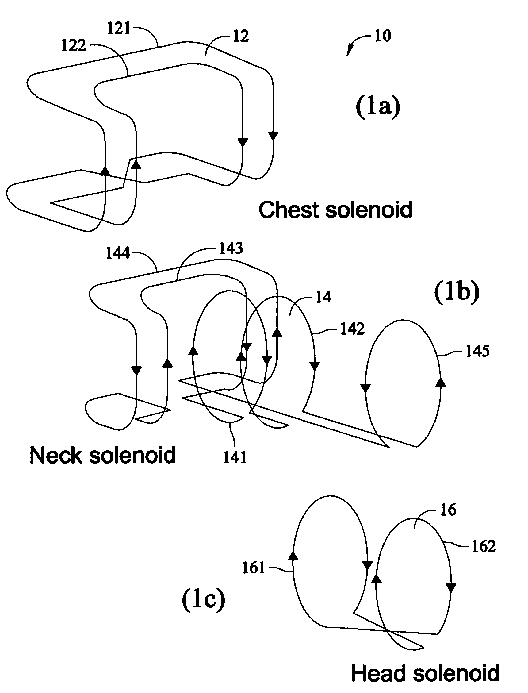
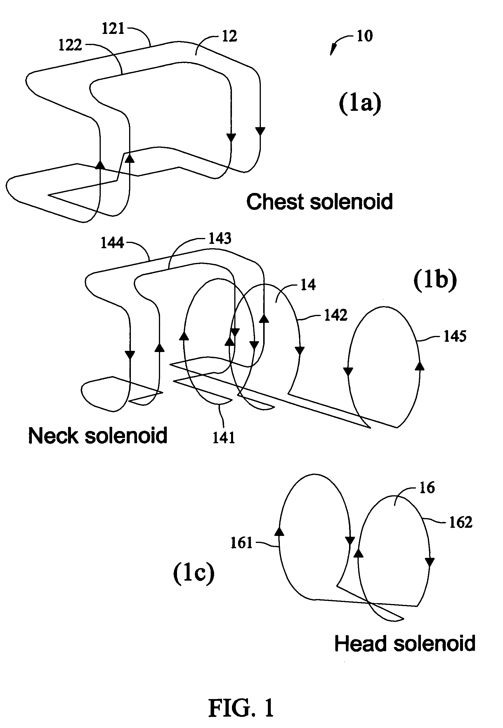
[0017]An array formed of coaxial solenoid coil elements can be effective in a vertical field system. Solenoidal coils have the advantage of good sensitivity, uniformity and naturally fit to various body parts for a vertical field system.

[0018]The challenge for solenoid based coil arrays lies in the decoupling between solenoidal coil elements. Effectively suppressing the “cross-talk” between active coil elements is a requirement in order to take advantage of high efficiency arrays through simultaneous acquisition of multiple coil elements.

[0019]Advanced coils using uneven counter-rotational (UCR) coil based solenoidal arrays (Su et al., U.S. patent application Ser. No. 10 / 085,347 issued as U.S. Pat. No. 7,221,974 and double counter-rotational (DCR) coils (Su et al., 10 / 098,268 issued as U.S. Pat. No. 6,768,303 have proven successful. These applications are incorporated herein by reference. These coils exhibit inherent decoupling between neighboring solenoid coil elements. A UCR may b...


PUM


Abstract

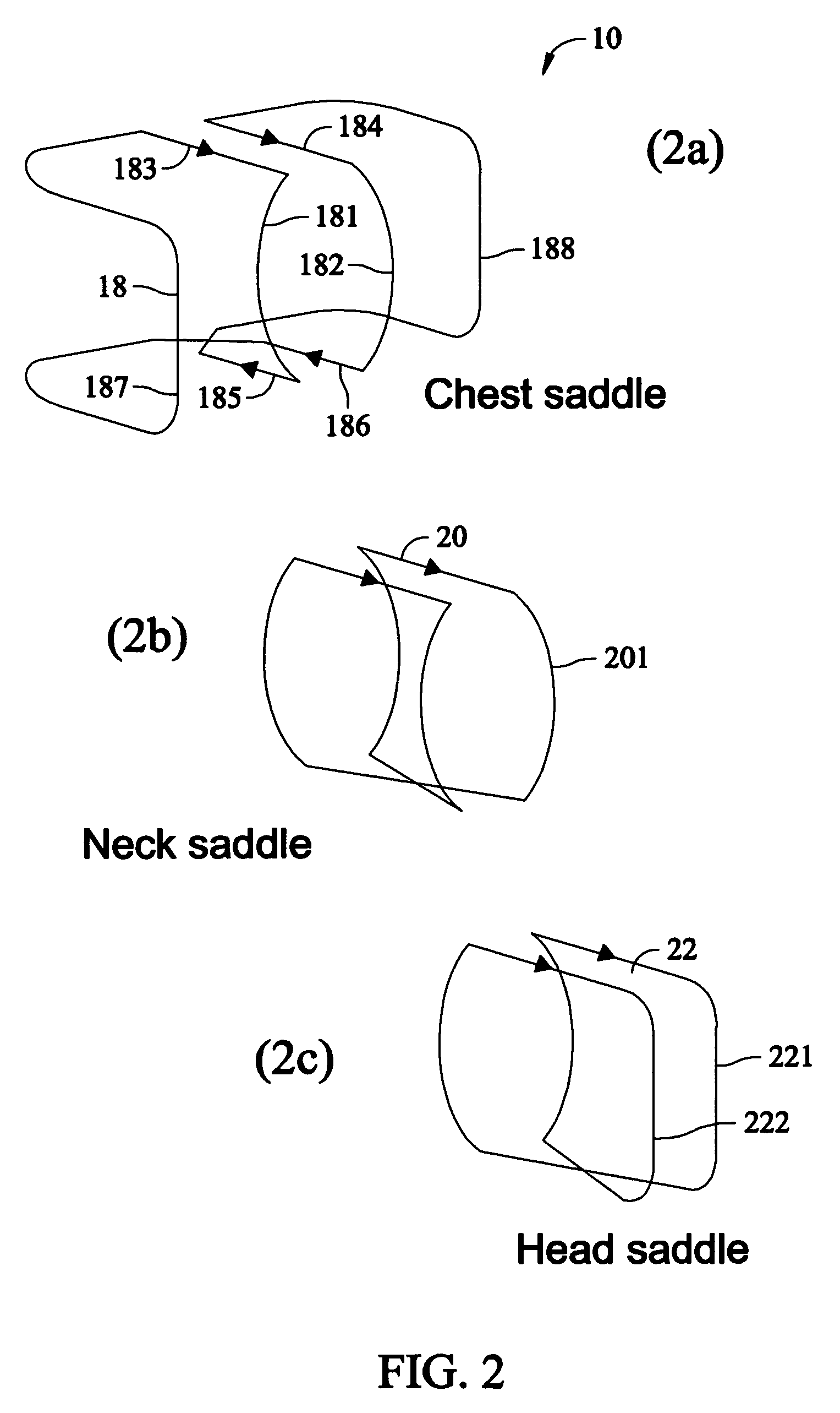
A vertical field MRI RF coil array for neurovascular imaging includes a head section having a solenoid coil element and a quadrature coil element; a neck section having a solenoid coil element and a quadrature coil element; and a chest section having a solenoid coil element and a quadrature coil element.

Description

CROSS-REFERENCE TO RELATED APPLICATIONS[0001]This application claims the benefit of U.S. provisional patent applications Ser. No. 60 / 302,185 filed Jun. 29, 2001, Ser. No. 60 / 276,297 filed Mar. 16, 2001, and Ser. No. 60 / 273,092 filed Mar. 2, 2001.[0002]This application is a continuation-in-part of U.S. patent application Ser. No. 10 / 085,347 filed Feb. 27, 2002 issued as U.S. Pat. No. 7,221,974 and Ser. No. 10 / 098,268 filed Mar. 15, 2002, issued as U.S. Pat. No. 6,768,303.BACKGROUND OF THE INVENTION[0003]The present invention relates to magnetic resonance imaging (MRI) and, in particular, to radio frequency (RF) coils.[0004]MRI has been widely used by radiologists as a powerful diagnostic tool. MRI techniques have several advantages including excellent soft tissue viewing and angiography. Neurovascular MRI has become a standard diagnostic procedure in the hospitals. Frequently, a neurovascular MRI protocol requires imaging coverage from the Circle of Willis to the aortic arch with a f...

Claims


Application Information

Patent Timeline
Patent Type & Authority Patents(United States)
IPC IPC(8): A61B5/055
CPCA61B5/0555A61B5/6814G01R33/34046G01R33/34053G01R33/34069G01R33/3415G01R33/3664G01R33/3678A61B5/055
Inventor SU, SUNYUZOU, MARK XUEMINGKITZMILLER, JEFF
Owner GENERAL ELECTRIC CO
Why Eureka
Try Eureka