Image forming apparatus

a technology of image forming apparatus and forming tube, which is applied in the direction of digital output to print unit, digitally marking record carrier, instruments, etc., can solve the problems of inability to achieve good recording, inability to apply stably electric charge, and failure of conveyan

Inactive Publication Date: 2008-02-26
RICOH KK
View PDF11 Cites 31 Cited by
  • Summary
  • Abstract
  • Description
  • Claims
  • Application Information

AI Technical Summary

Benefits of technology

[0012]It is a general object of the present invention to provide an improved and useful image forming apparatus in which the above-mentioned problems are eliminated.
[0013]A more specific object of the present invention is to provide an image forming apparatus that can form a high-quality image while acquiring a stable conveyance performance.
[0015]According to the above-mentioned invention, since the conveyance speed is controlled in accordance with the charge period length of the positive and negative electric charges applied onto the conveyance belt, a stable application of the electric charges can be performed on the conveyance belt, and, both the attracting force necessary for conveyance and suppression of a surface potential can be achieved simultaneously. Additionally, a high-quality image can be stably formed without an offset in landing positions of liquid droplets and a reverse flow of liquid mist toward the recording head.
[0017]According to the above-mentioned invention, since the charge period length is changed by adjusting the period of the positive and negative electric charges when the charge period length is equal to or longer than a predetermined charge period length, and the charge period length is changed by adjusting the conveyance speed when the charge period length is shorter than the predetermined charge period length, a stable application of the electric charges can be performed on the conveyance belt, and, both the attracting force necessary for conveyance and suppression of a surface potential can be achieved simultaneously. Additionally, a stable conveyance performance can be acquired, and a high-quality image can be stably formed without an offset in landing positions of liquid droplets and a reverse flow of liquid mist toward the recording head.

Problems solved by technology

Thus, there is a problem in that a good recording cannot be achieved due to a turbulent flow and also ink mist generated by the flow of ink droplets may flow reversely and adhere to a head discharge part.
Accordingly, electric charge cannot be applied stably and charge fluctuation occurs, which results in fluctuation in an attraction force necessary for conveying the paper, which consequently causes conveyance failure.
Additionally, there are problems in that: a sufficient charge cannot be applied to a conveyance belt since there is a limitation in the response speed of the output of a high voltage power supply; a failure may occur in the high-voltage power source if the conveyance speed is increased forcibly; and pin holes may be formed in the conveyance belt due to insulation destruction caused by a local high-voltage being generated.

Method used


Image

  • Image forming apparatus
  • Image forming apparatus
  • Image forming apparatus

Examples


first embodiment

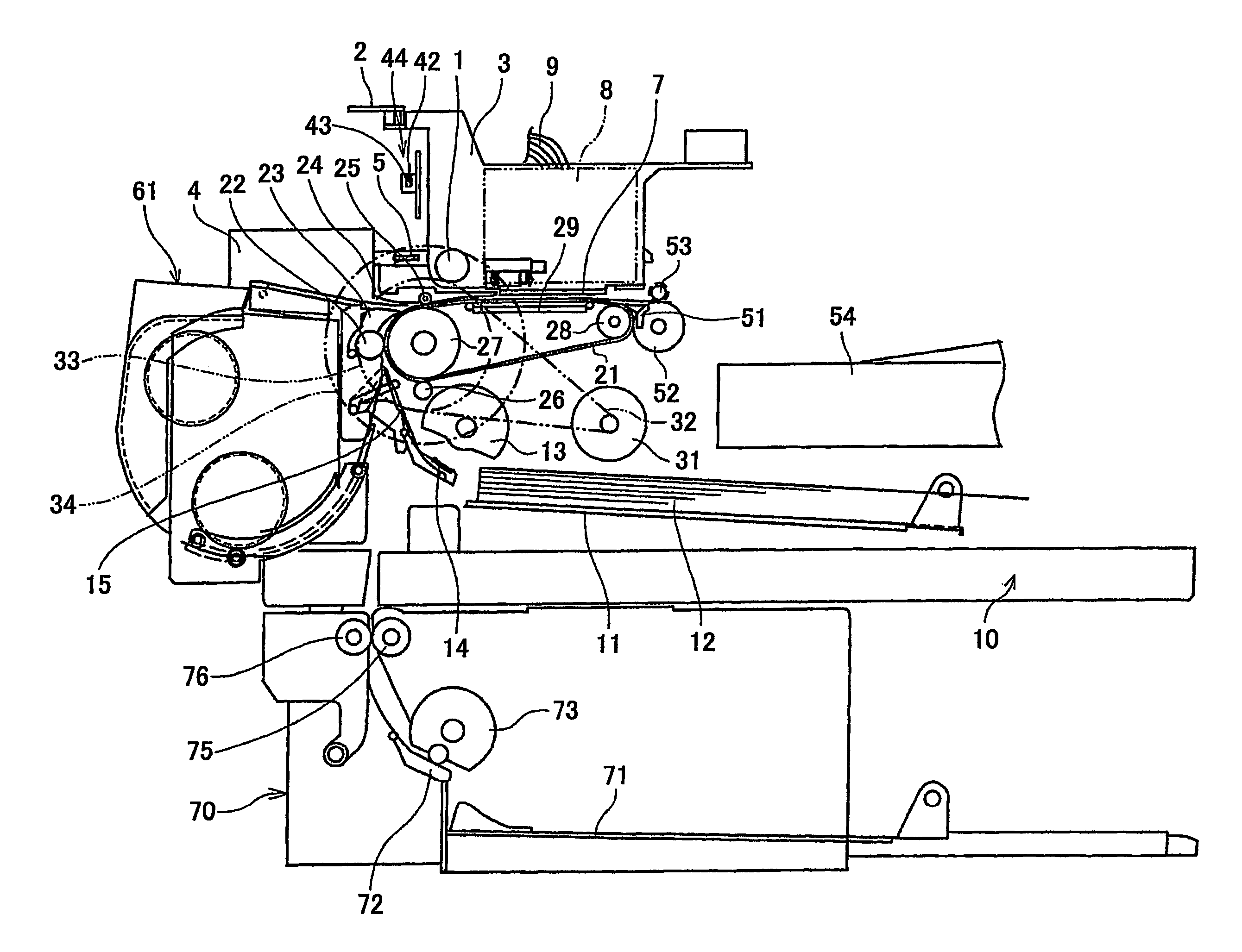
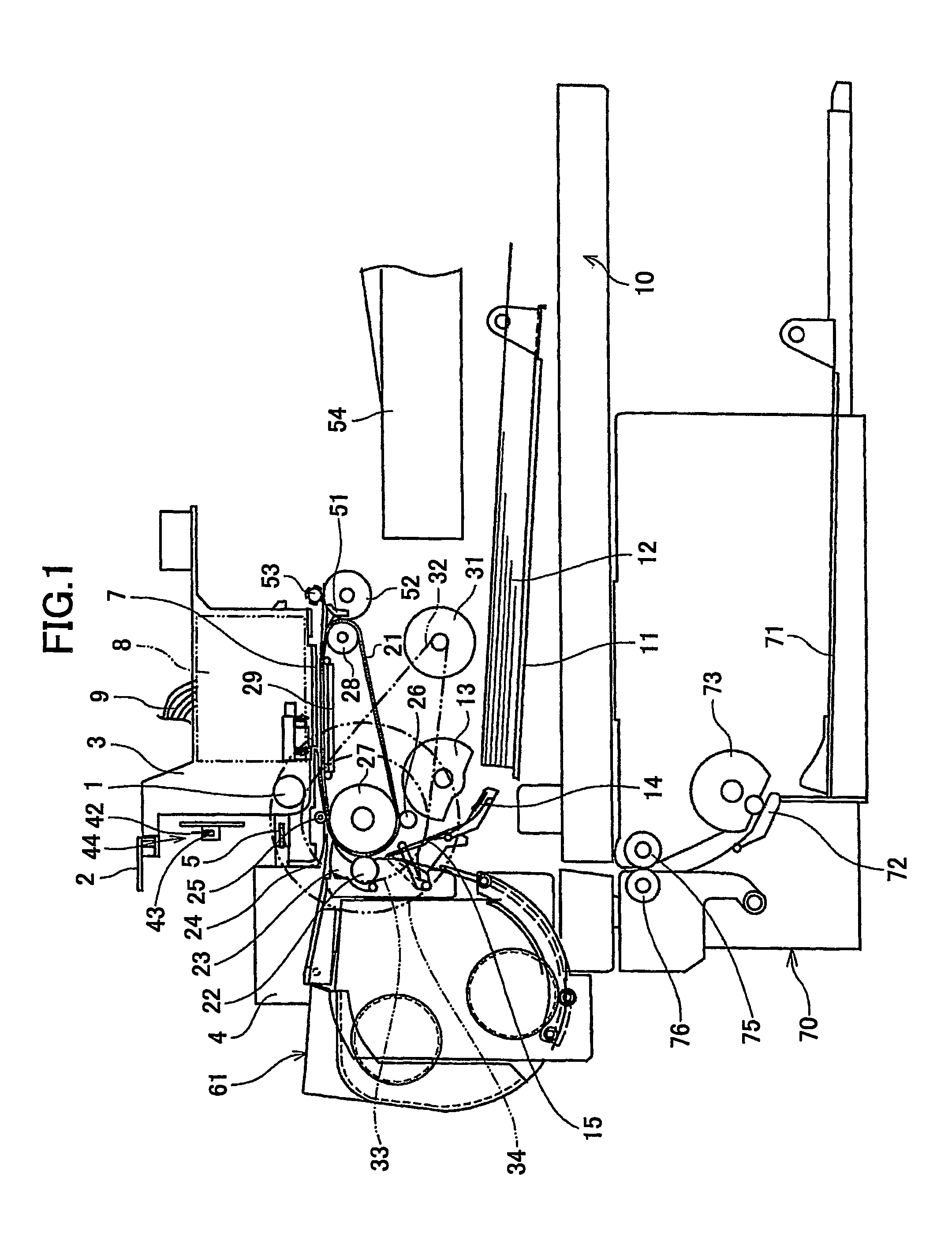
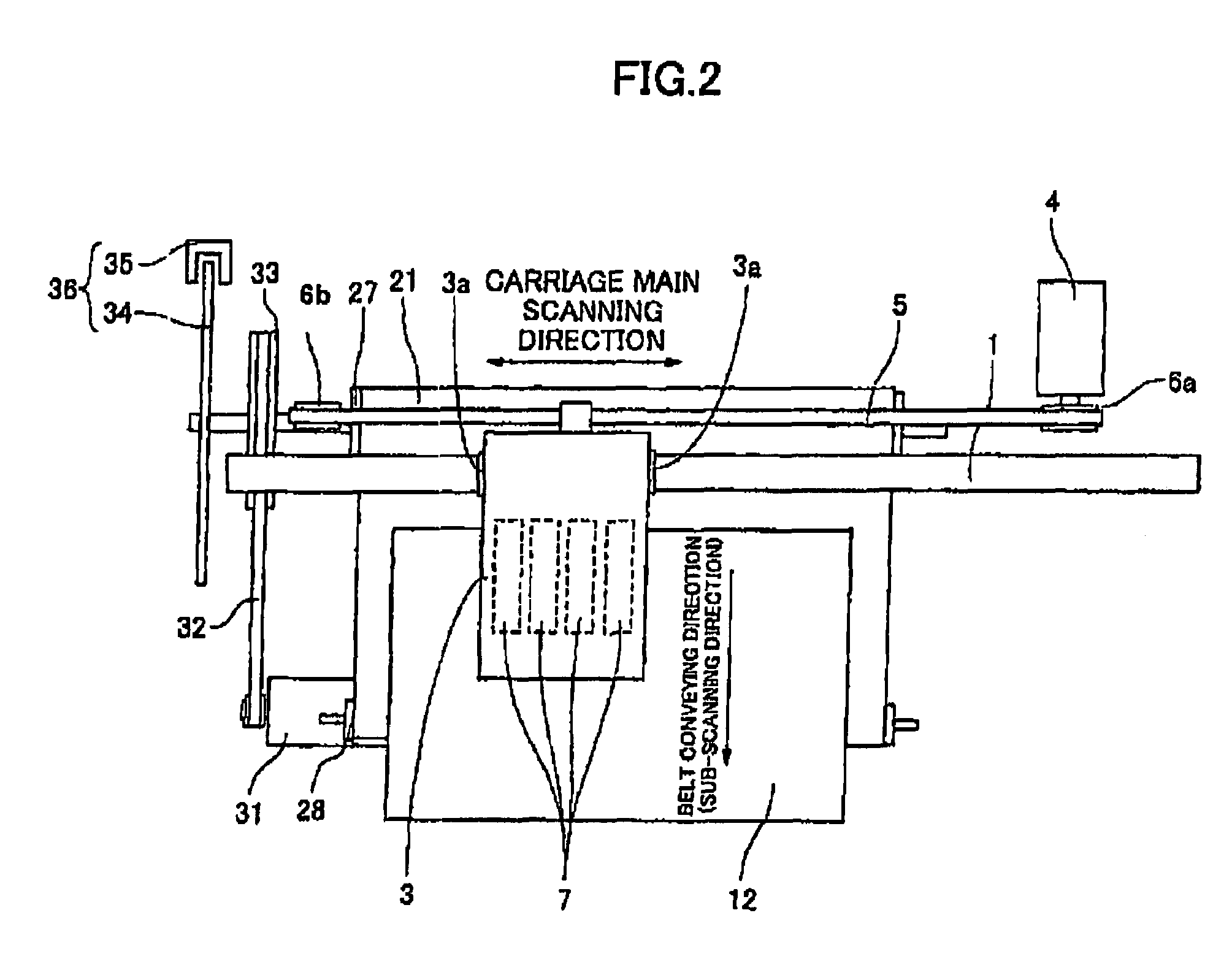
[0040]First, a description will be given, with reference to FIGS. 1 and 2, of an image forming apparatus according to the present invention. FIG. 1 is an illustrative side view of the image forming apparatus. FIG. 2 is a plan view of a part of the image forming apparatus shown in FIG. 1.

[0041]In the image forming apparatus shown in FIG. 1, a carriage 3 is slidably supported by a guide rod 1 and a guide rail 2 that bridge between left and right side plates (not shown in the figure) in a main scanning direction so that the carriage 3 is moved to scan in directions of arrows (the main scanning direction) in FIG. 2 by a main scanning motor via a timing belt being engaged with a drive pulley 6a and an idle pulley 6b. It should be noted that guide bushings (bearings) 3a are interposed between the carriage 3 and the guide rod 1, respectively.

[0042]Four recording heads 7 which consist of liquid droplet discharge heads, which discharge ink droplets of yellow (Y), cyan (C), magenta (M) and bl...

third embodiment

[0106]A description will now be given, with reference to FIGS. 11 and 12, of an image forming apparatus according to the present invention. FIG. 11 is a timing chart showing an example of a speed profile of the conveyance belt and an output signal waveform of the AC bias supply part. FIG. 12 is an illustration for explaining a charge pattern on the conveyance belt.

[0107]In the above-mentioned first embodiment, the conveyance speed is adjusted in accordance with the charge period length. That is, when the charge period length is small, a stable attraction is achieved by decreasing the conveyance speed. However, a decrease in the conveyance speed by result in a decrease in a printing speed, and, thus, it is preferable to prevent the conveyance speed from decreasing as much as possible. Considering conveyance, although it is preferable to attract an entire recording paper, a quality and stability of conveyance can be maintained if local attraction areas are provided with a predetermine...

fourth embodiment

[0118]A description will now be given, with reference to FIGS. 13 and 14, of an image forming apparatus according to the present invention. FIG. 13 is a timing chart showing an example of a speed profile of the conveyance belt and an output signal waveform of the AC bias supply part. FIG. 14 is an illustration for explaining a charge pattern on the conveyance belt.

[0119]In the above-mentioned third embodiment, positive and negative charges can be applied to the conveyance belt 21 without decreasing the conveyance speed, that is, a maximum speed during a line feed operation, by applying electric charges at a period from a state where the conveyance belt is stopped until a predetermined conveyance speed is reached in a line feed operation. This uses the fact that the conveyance speed is low during a period for raising the conveyance speed to the predetermined speed since it takes a considerable time to raise the conveyance speed.

[0120]On the other hand, in the fourth embodiment, atten...


PUM


Abstract

An image forming apparatus can form a high-quality image while acquiring a stable conveyance performance. A conveyance belt (21) conveys a recording medium (12) by attracting the recording medium (12) by an electrostatic force. A recording head (7) discharges liquid droplets toward the recording medium (12) being conveyed by the conveyance belt (21). Alternating positive and negative electric charges are applied onto the conveyance belt (21). A conveyance speed is controlled in accordance with a charge period length of the alternating positive and negative electric charges applied onto the conveyance belt (21).

Description

TECHNICAL FIELD[0001]The present invention relates to image forming apparatuses and, more particularly, to an image forming apparatus provided with a conveyance belt for conveying a recording medium.BACKGROUND ART[0002]There is known, for example, an inkjet recording apparatus as an image forming apparatus such as a printer, a facsimile or a copy machine apparatus. An inkjet recording apparatus performs recording by discharging ink droplets from a recording head onto a recording medium such as a recording paper (hereinafter, simply referred to as a “paper” but material is not limited to a paper). The inkjet recording apparatus is capable of recording a fine image at a high speed with advantages such as a low running cost, a low noise and an easy color image recording using multi-color ink.[0003]In such an inkjet recording apparatus, it is required to increase a positional accuracy of landing positions of ink droplets on a paper so as to improve an image quality. There is known, such...

Claims


Application Information

Patent Timeline
Patent Type & Authority Patents(United States)
IPC IPC(8): B41J2/01B41J29/38B41J11/00B41J11/42B65H5/00
CPCB41J11/007B41J11/42B65H5/004B41J2/01
Inventor KOGURE, SEIICHIIMOTO, SHINJI
Owner RICOH KK
Why Eureka
Try Eureka