Shroud enclosed inverted surface piercing propeller outdrive

a propeller and inverter technology, applied in waterborne vessels, marine propulsion, vessel construction, etc., can solve problems such as not allowing the driven hull to be driven

Inactive Publication Date: 2008-02-26
HOWARD M ARNESON TRUSTEE OF THE HOWARD M ARNESON TRUST DATED AUGUST 3 2016
View PDF18 Cites 14 Cited by
  • Summary
  • Abstract
  • Description
  • Claims
  • Application Information

AI Technical Summary

Benefits of technology

[0042]An advantage of the inverted shroud is that it effectively defines a channel in the water in which the partially immersed propeller can operate. Forces tending to cause the partially immersed propeller to “walk” or steer the boat by causing “helm” (steering bias) are controlled. Specifically, the shroud created channel isolates the outdrive from reacting with the water to either side of the propeller.
[0043]An additional advantage of the inverted shroud is that it provides a smooth acceleration of the watercraft to cruising speed. It is not accompanied by propeller spinning at high speed with propeller cavitation to the surrounding water. Further, at low planing speeds, the outdrive tends to maintain planing and does not allow the driven hull to “fall” off of the plane and into the water in a displacement mode.
[0044]Further, the inverted shroud can itself be adjusted in pitch, either with the angle of the outdrive or independent of the angle of the outdrive. This adjustment in pitch of the shroud can trim lifting forces on the hull of the high speed boat being propelled by the outdrive. In the usual case, adjustments in shroud trim will be made to avoid undue stern lift and reactive pressure pushing the bow of the high speed boat into the water.
[0045]An advantage of the plate overlying the departure side of the partially immersed outdrive propeller blading is that it confines water over the departure blading at a level well above the “undisturbed” water line. Propeller blades, departing a plane above the normal water line, pass through a layer of water that is elevated above the plane of where the water would be, if it was undisturbed. In such passage, it is possible for the “lower pitch” departure blading to exert a propelling effect on the water.
[0047]Second, even when the boat is at full (high) speed, I find that the “low pitch” portion of the propeller is much more efficiently utilized. Being that the low pitch portion of the propeller has an increased “dwell time” in the passing water, the propulsion contribution of the low pitch departure blading is increased by the overlying plate.
[0049]A further advantage of both the plate and the inverted shroud is that it provides the propeller with protection. While debris can conceivably be introduced into the interstices between the propeller, plate and inverted shroud, in the usual case debris will be deflected. In most cases, debris not deflected will be pulverized.

Problems solved by technology

Further, at low planing speeds, the outdrive tends to maintain planing and does not allow the driven hull to “fall” off of the plane and into the water in a displacement mode.

Method used


Image

  • Shroud enclosed inverted surface piercing propeller outdrive
  • Shroud enclosed inverted surface piercing propeller outdrive
  • Shroud enclosed inverted surface piercing propeller outdrive

Examples


Embodiment Construction

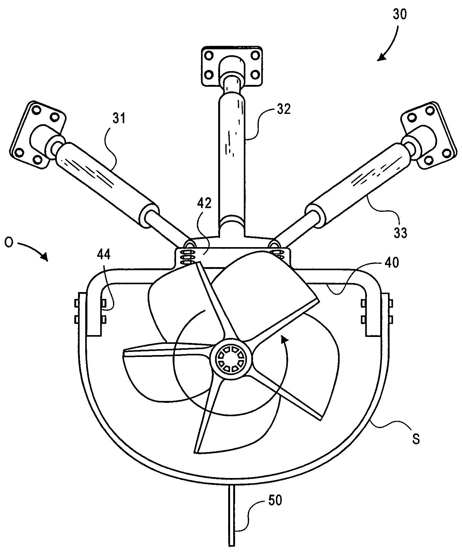
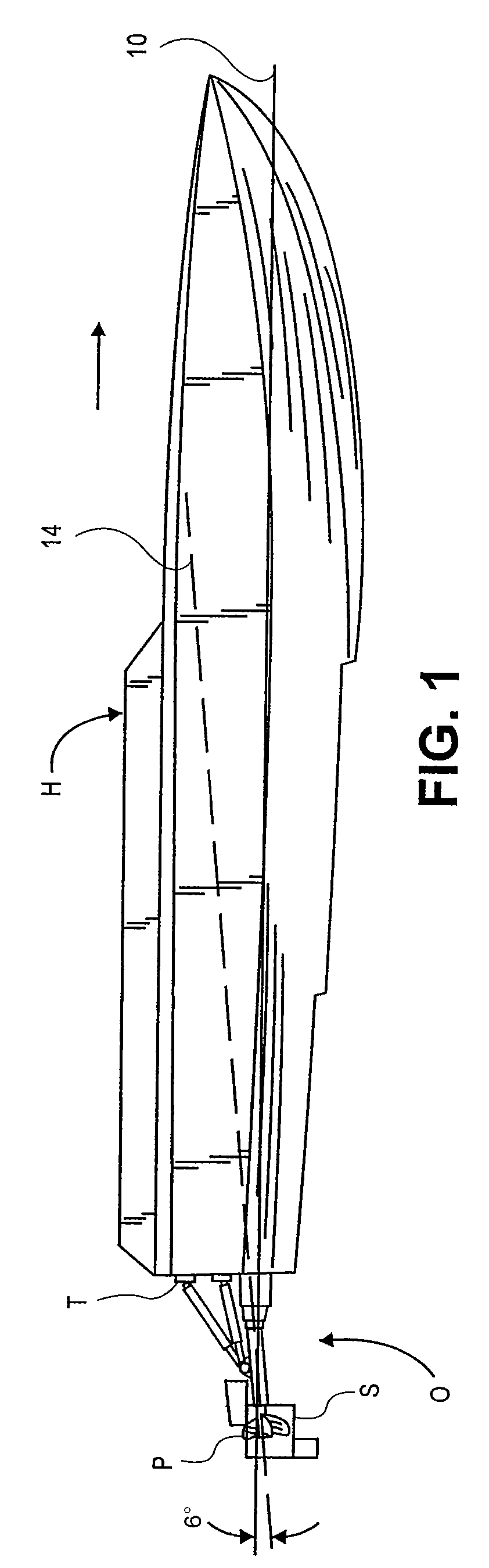
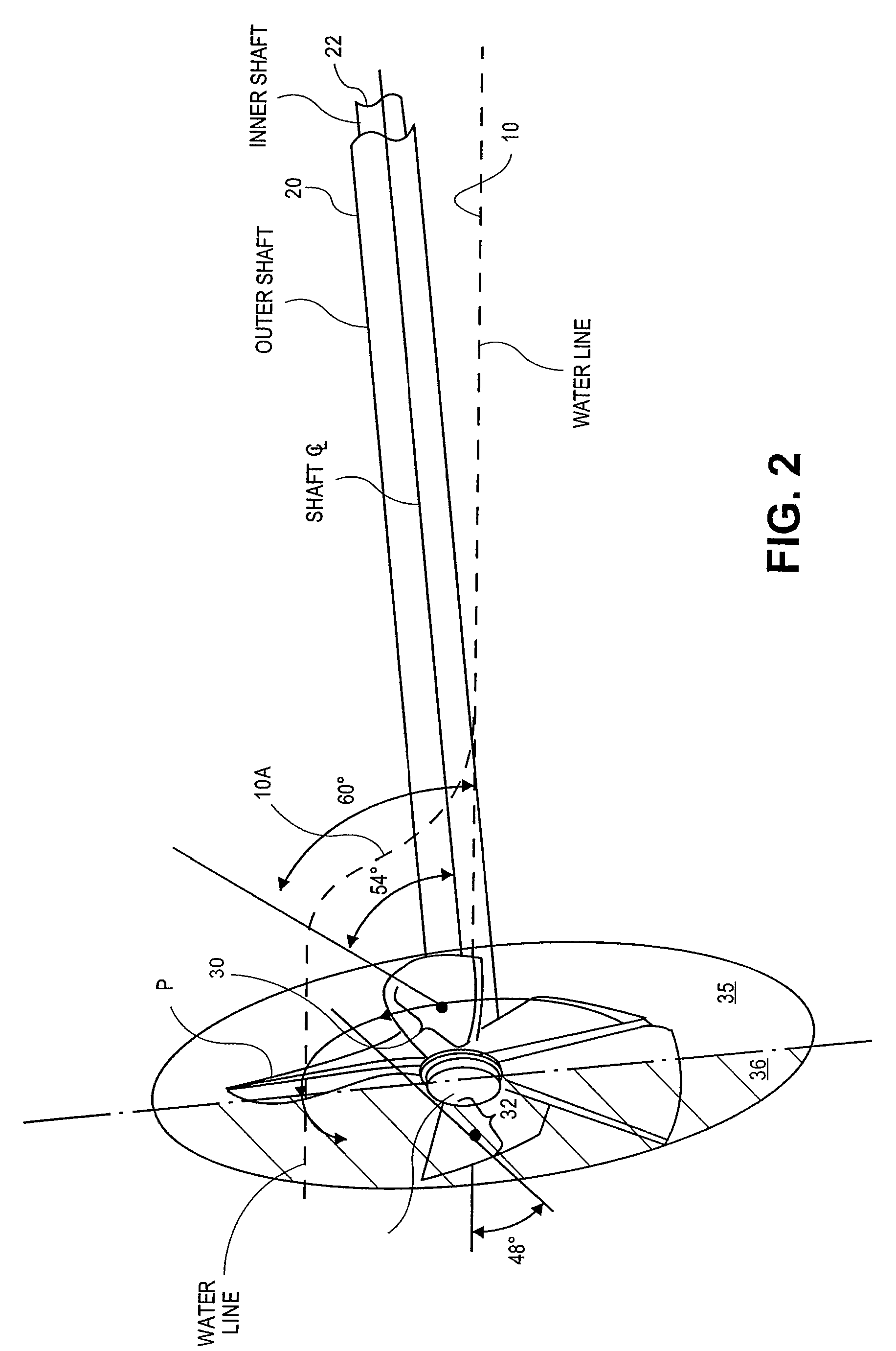
[0059]Referring to FIG. 1, high speed planing hull H having transom T has outdrive O. Hull H passes over water having upper surface 10. Outdrive O has partially immersed propeller P surrounded by shroud S which below, around and adjacent the propeller.

[0060]Referring further to FIG. 1, the most important thing to note is the angle between the plane of upper surface 10 of the water and centerline 14 of outdrive O shaft. Specifically, outdrive O has an angle of 6° with respect to upper surface 10. This angle can vary. In a wide range, this angle can be from 3° to 12°. In a narrower range, this angle can be from 4° to 9°. Here it is illustrated at the preferred angle of about 6°. Further, it will be understood that these angles are taken when the hull H is underway in a planing disposition at air speeds in the range of 30 mph to 160 mph. I avoid air speeds above 160 mph because of the danger of hull H becoming airborne.

[0061]Hull H is on the order of 50 feet in length with a displaceme...


PUM


Abstract

A shrouded outdrive propels a high-speed boat having a hull for high-speed passage through water. The hull has at least one bow at the forward end and at least one transom at the stern. A tubular shaft extends at a small angle (6° to 12°) from the boat transom into the water, and a drive shaft is arranged within the tubular shaft. A propeller is mounted to the drive shaft for partial immersion in the water so that a lower portion of the propeller extends into the water during high-speed floating passage of the boat and a upper portion of the propeller is above the water during high-speed floating passage of the boat. A shroud is arranged about the propeller and is disposed below the water and adjacent the propeller. A mount holds the shroud to form a shroud-enclosed channel during high-speed passage of the boat through the water in which the propeller rotates. A plate horizontal to the undisturbed passing water surface overlies the departure side of the propeller at a radial distance of about two thirds (⅔) of the radius of the propeller. This plate immediately abuts the departure blading of the propeller in the direction of boat movement through the water and assures immersion of the lower pitch departure side of the partially immersed propeller in water for more efficient propulsion. Embodiments are disclosed where the plate is utilized as the necessary support for the shroud. Additionally, both the shroud and the plate can have small angular variations with respect to the surface of the undisturbed surface through which the high-speed hull passes.

Description

[0001]This invention relates to outdrives for boats having partially immersed surface piercing propellers. More particularly, a high speed boat is provided with a surface piercing propeller enclosed within an inverted shroud which effectively defines a channel isolating the propulsion effects of the outdrive from extraneous torques common in surface piercing propeller outdrives. Moreover, an overlying plate improves propeller performance on the departure portion of the propeller blading from the partially immersed propeller.[0002]It will be understood that the outdrive disclosed herein is applicable to all planing hulls—usually proceeding at speeds in excess of 18 mph. This disclosure relates to patrol boats, yachts, mega yachts, and so-called speed boats. Regarding ski boats, it is to be understood that the outdrive herein generates a “rooster tail”, a stream of airborne elevated water propelled by the propeller immediately astern of the outdrive. For that reason, the outdrive is n...

Claims


Application Information

Patent Timeline
Patent Type & Authority Patents(United States)
IPC IPC(8): B63H1/28B63H5/14
CPCB63H1/14B63H5/1252B63H5/165B63H2001/185
Inventor ARNESON, HOWARD
Owner HOWARD M ARNESON TRUSTEE OF THE HOWARD M ARNESON TRUST DATED AUGUST 3 2016
Why Eureka
Try Eureka