Valved connector with closure operated by axial movement of the valve

a valve connector and valve technology, applied in the field of valve connectors, can solve the problems of leaking blood, impede, divert or damage the catheter, deformation or damage of fragile catheters or instruments,

Inactive Publication Date: 2008-02-26
ARTHESYS
View PDF15 Cites 55 Cited by
  • Summary
  • Abstract
  • Description
  • Claims
  • Application Information

AI Technical Summary

Benefits of technology

[0009]Therefore, it is a principal object of the present invention to resolve the technical problems in the prior art by providing a valved connector that provides the passive sealing advantages of the

Problems solved by technology

A problem arises when inserting a fragile or highly flexible catheter or instrument through such a hemostasis valve or sealing device.
The fragile catheter or instrument may be deformed or damaged as it passes through the hemostasis valve or sealing device.
In addition, many known valved connectors and fittings contain other obstacles to passage of a catheter or instrument, such as internal steps or cavities, abrupt tapers and side passages that may impede, divert or damage the catheter or instrument during insertion.
This problem is of particular concern when using extremely flexible or fragile micro-guidewires and micro-catheters or when using assemblies mounted and maintained by friction or crimping, like for example a stent mounted on a balloon of a dilatation catheter.
The disadvantage of this system is connected with the principle of the compression sealing mechanism.
To permit the movement of the catheters introduced, one must loosen the threaded cap thereby provoking leaking of blood.
These necessary manipulations are a significant inconvenience to the physician during a catheter procedure.
Movement of the inserted catheter without loosening the valve can easily damage a delicate catheter or ins

Method used


Image

  • Valved connector with closure operated by axial movement of the valve
  • Valved connector with closure operated by axial movement of the valve
  • Valved connector with closure operated by axial movement of the valve

Examples


first embodiment

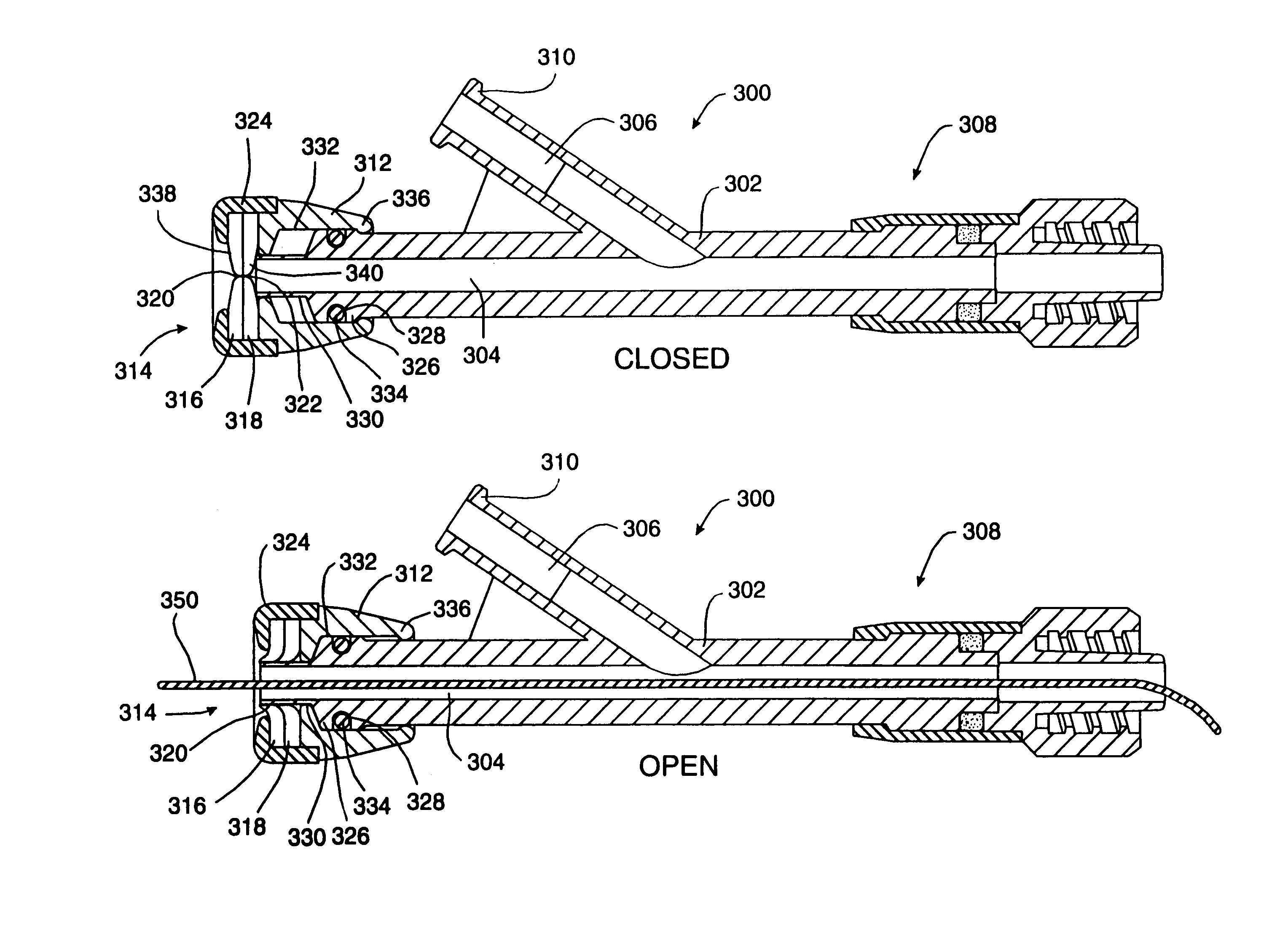
[0032]FIG. 5 shows a valved connector apparatus 300 constructed according to the present invention. The valved connector apparatus 300 may take any one of many possible physical configurations. For example, the valved connector apparatus 300 may be integrated into the proximal end of another device, such as a catheter, a guiding catheter, an introducer sheath or a surgical access cannula. Alternatively, the valved connector apparatus 300 may be configured as a separate component that is adapted for attachment to another device, such as a catheter, a guiding catheter, an introducer sheath or a surgical access cannula. In one particularly preferred embodiment of the invention, illustrated in FIG. 5, the valved connector apparatus 300 is configured with a Y-shaped connector body 302 having a main channel 304 and a lateral channel 306 branching off of the main channel 304. Preferably, the inner diameter of the main channel 304 is smooth and continuous all the way through the Y-shaped co...

second embodiment

[0038]FIG. 7 shows a valved connector apparatus 400 constructed according to the present invention. As with the previously described embodiment, the valved connector apparatus 400 may take any one of many possible physical configurations, including as a separate or integral component for use with a catheter, a guiding catheter, an introducer sheath or a surgical access cannula. A particularly preferred embodiment of the invention is illustrated in FIG. 7 having a Y-shaped connector body 402 with a main channel 404 and a lateral channel 406 branching off of the main channel 404. The inner diameter of the main channel 404 is preferably smooth and continuous all the way through the Y-shaped connector body 402 without abrupt steps, exposed edges or severe tapers. The Y-shaped connector body 402 has a first attachment mechanism 408, such as a rotatable male luer lock fitting or the like, connected to the distal end of the main channel 404, and a second attachment mechanism 410, such as a...


PUM


Abstract

A valved connector apparatus is described having an integral opening and closing system operated by axial movement of the valve. The body of the valved connector apparatus is in a Y-shaped configuration with a main channel and a lateral channel branching off of the main channel. A normally dosed, passive hemostasis valve is housed in a valve body that is slidably connected to the proximal end of the main channel. The hemostasis valve is opened by sliding the valve body distally with respect to the Y-shaped connector body so that a cylindrical extension extending from the proximal end of the Y-shaped connector body penetrates a central opening in the hemostasis valve, creating an open passage for insertion of guidewires, catheters or other instruments. The valved connector apparatus allows safe introduction of extremely flexible or fragile guidewires, catheters or other instruments.

Description

FIELD OF THE INVENTION[0001]The present invention relates to a valved connector with an integral opening and closing system operated by axial movement of the valve. The valved connector has many applications in the area of cardiovascular catheters and surgical instruments, particularly as a hemostasis valve on a cardiovascular catheter or introducer sheath. The valved connector can equally be used in connection with catheters and surgical instruments used in other body canals, such as the esophagus or urethra.BACKGROUND OF THE INVENTION[0002]It is frequently necessary in the course of catheterization procedures and many surgical procedures to insert one catheter or instrument through a passage or lumen in another catheter or instrument. To avoid bleeding or loss of other fluids through the annular space between the two catheters or instruments it is typical to employ a hemostasis valve or other sealing device at the proximal end of the outer catheter or instrument. The inner cathete...

Claims


Application Information

Patent Timeline
IPC IPC(8): A61M1/00A61M39/00F16K15/14A61M39/06
CPCA61M39/06
Inventor HILAIRE, PIERRE
Owner ARTHESYS
Why Eureka
Try Eureka