System and method for charging and discharging a superconducting coil

a superconducting coil and charging system technology, applied in the field of superconducting coil charging and discharging system, can solve the problems of heavy and relatively slow conventional phase control thyristor field exciters, and achieve the effects of reducing size and weight, preventing quenching in the coil, and low rippl

Inactive Publication Date: 2008-02-26
GENERAL ELECTRIC CO
View PDF28 Cites 25 Cited by
  • Summary
  • Abstract
  • Description
  • Claims
  • Application Information

AI Technical Summary

Benefits of technology

[0004]The present invention provides efficient, compact and light-weight field exciters enabling variable voltage levels to be achieved from a single low voltage source. Additionally, schemes to reduce switching losses are provided that switch to high voltage only when a fast current change is needed. The lower voltage bus is used during most steady state operations, thus reducing stresses and increasing efficiency.
[0006]The invention has several important advantages. First, the light weight and compact design allows it to be used in applications where space is limited and weight is a consideration, such as on aircraft. Additionally, the ability to use only a low voltage source or bus to provide a high voltage to the coil is advantageous where only a low voltage supply is available, such as an aircraft dc bus. The invention also provides very low ripple in the output voltage to prevent quenching in the coil eliminating the need for additional filters, thus reducing size and weight. Finally, switching losses are reduced, making the circuit more efficient.
[0007]Several configurations are disclosed that provide additional utility. One configuration provides for redundancy of buck converters which further reduces the ripple in the output. The redundancy also provides a level of security in that if one of the buck converters fails, the other can still operate to provide the appropriate voltage level to the coil. Another configuration provides gross and fine tuning of the voltage that is applied to the coil. This is achieved by stacking a high voltage booster bridge with a low voltage supplier bridge. Yet another configuration allows the multi-level field exciter to regenerate a battery or to put excess power back onto a power supply bus. It should be understood that these configurations are representative configurations and the invention may have many other configurations and applications not specifically described herein.

Problems solved by technology

Conventional phase controlled thyristor field exciters are heavy and relatively slow.

Method used


Image

  • System and method for charging and discharging a superconducting coil
  • System and method for charging and discharging a superconducting coil
  • System and method for charging and discharging a superconducting coil

Examples


Embodiment Construction

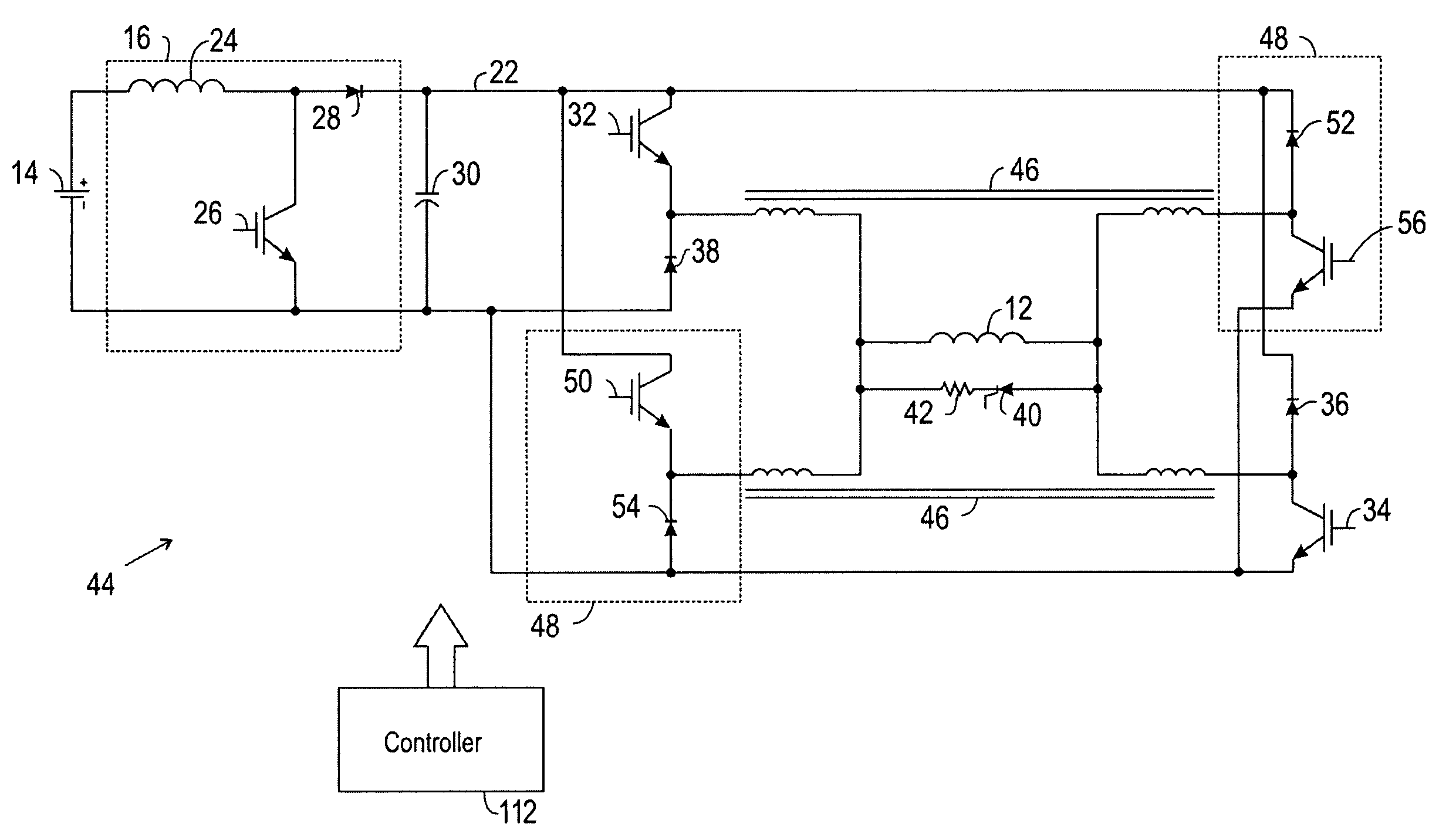
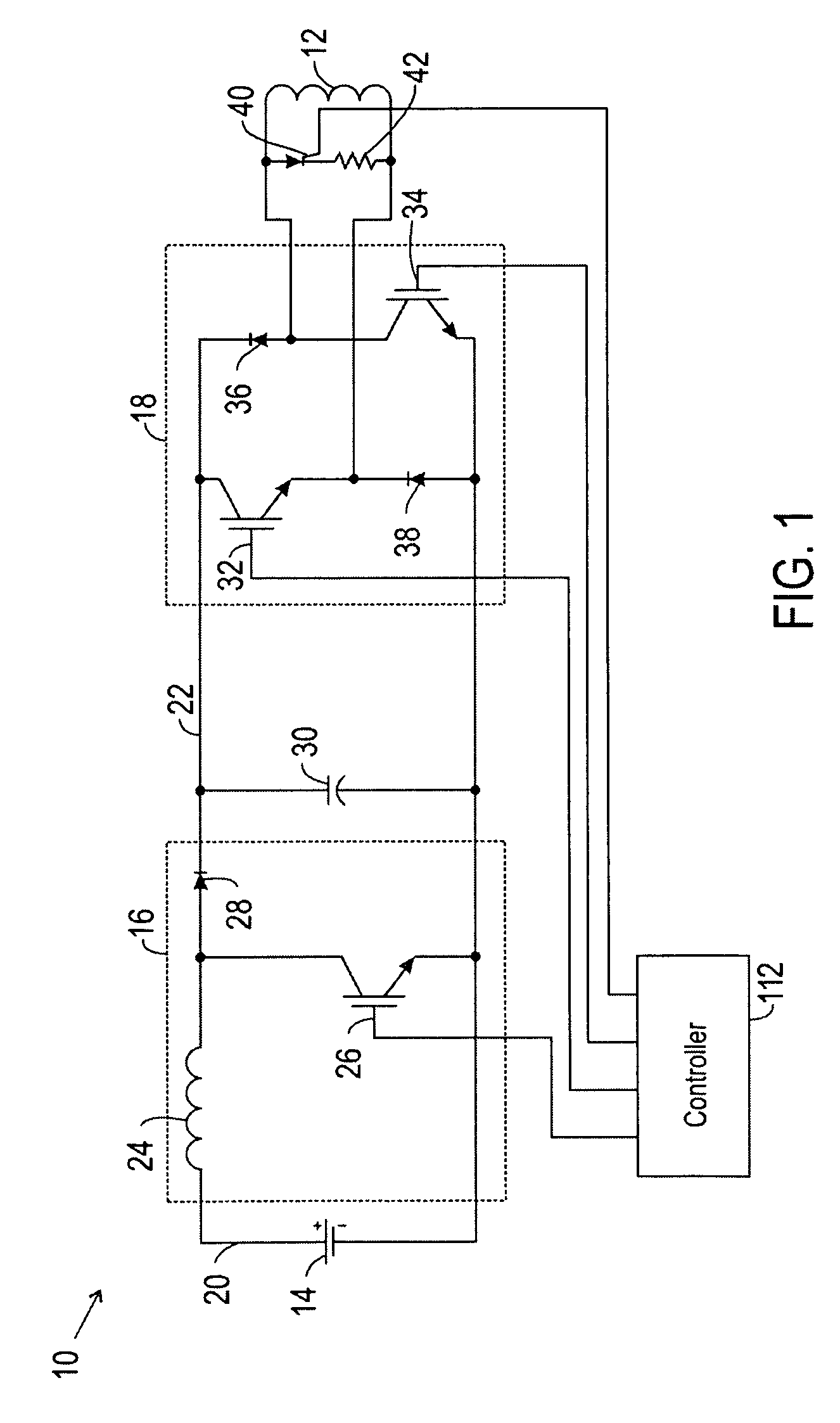
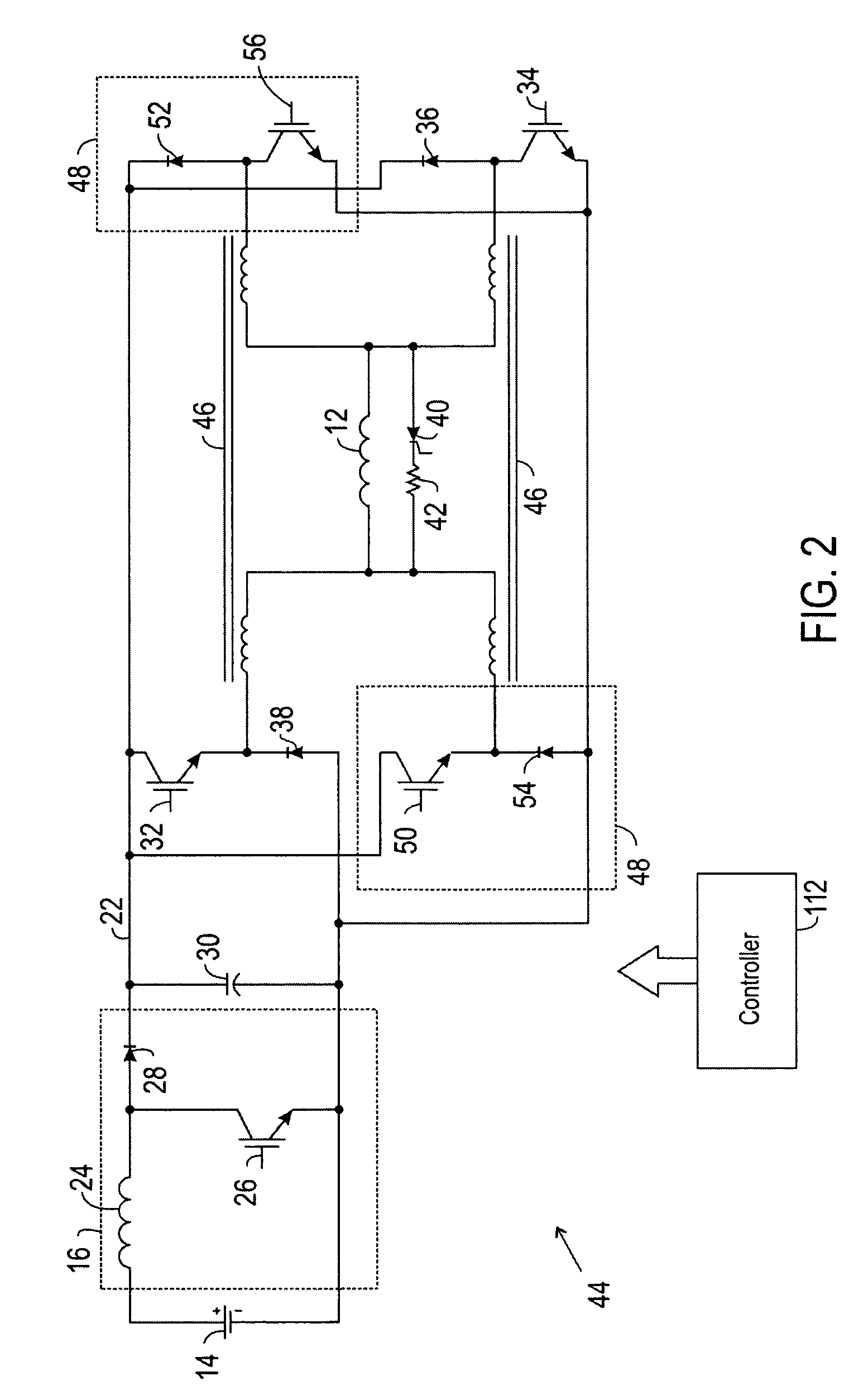
[0014]FIG. 1 schematically illustrates the power supply circuit 10 for providing excitation current to a superconducting coil 12. The circuit 10 includes a boost converter 16, and a buck converter 18. The boost converter 16 is configured to convert a low dc voltage to a high dc voltage. The low voltage dc power is supplied on a low-voltage dc bus 20, while the high voltage dc power is output on a high voltage dc bus 22.

[0015]The boost converter 16 includes an inductor 24 and a solid state switch 26. The switch 26 is coupled across the dc bus and may be switched, typically in a pulse width modulated regime, to convert electrical power from the low voltage bus 20 to a higher voltage that is applied to the high voltage dc bus 22 as described below. A capacitor 30 is electrically coupled in parallel to the solid state switch 26 and stores the higher voltage. A diode 28 prevents flow of current back from the high voltage dc bus 22 to the boost converter 16.

[0016]The buck converter compri...


PUM


Abstract

A system and method for charging and discharging a superconducting coil. The system comprising a boost converter coupled between a low-voltage bus and a high voltage bus, and a buck converter coupled between the high-voltage bus and the coil. The system being configured to charge and discharge the coil without reversing the current while reversing polarity, and to only supply high-voltages when necessary. The system further comprising means to dissipate excess energy during discharge. The method comprising pulse width modulating the solid-state switch of a boost converter to achieve a high-voltage from a low-voltage and then switching solid-state switches of a buck regulator to charge or discharge the coil in a non current reversing, polarity reversing manner.

Description

BACKGROUND[0001]The invention relates generally to power supplies for high inductance, low impedance loads, such as superconducting coils. The invention may be employed, for example, with field exciters for electrical machines and more particularly to machines with large field inductances such as superconductor machines.[0002]High inductance, low impedance machines require high voltages in order to achieve fast field current response. The high voltages are typically only needed for brief periods and it is advantageous to avoid application of high voltages when there is no need to do so. Additionally, in some applications only a low dc voltage is available, and therefore there is a need to produce a high voltage for a load from the low dc voltage source.[0003]Conventional phase controlled thyristor field exciters are heavy and relatively slow. There is a need in the art for improved arrangements for exciting electrical machines that include superconductive coils and windings.BRIEF DE...

Claims


Application Information

Patent Timeline
Patent Type & Authority Patents(United States)
IPC IPC(8): G05F1/62G05F1/59
CPCH01F6/006H02M3/158H02M3/3353H02M2001/007H02M2003/1555H02M1/007H02M3/1555
Inventor STEIGERWALD, ROBERT LOUISGARCES, LUIS JOSE
Owner GENERAL ELECTRIC CO
Why Eureka
Try Eureka