Apparatus for current measurement

a current sensor and apparatus technology, applied in the direction of galvano-magnetic devices, measurement using dc-ac conversion, instruments, etc., can solve the problems of high complexity of the design of the known apparatus, limited operation range of the current sensor, and limited use of magnetoresistive materials. the effect of reducing the size of the known apparatus

Inactive Publication Date: 2008-02-26
SIEMENS AG
View PDF17 Cites 31 Cited by
  • Summary
  • Abstract
  • Description
  • Claims
  • Application Information

AI Technical Summary

Benefits of technology

[0008]An object of an embodiment of the present invention is to refine the known current measurement apparatuses so as to simplify their design for adequate sensitivity.
[0010]This refinement of the current measurement apparatus advantageously makes it possible to design its at least one current sensor element in a simple manner: A loop which is magnetically virtually completely closed, in particular in the form of a ring or sleeve, and composed of metallic or, in particular, non-metallic magnetoresistive material is located in the magnetic field circuit of the current-carrying electrical conductor, and is conductively isolated from it by a thin insulation layer. This loop has a predetermined, pronouncedly axial extent, which is considerably greater than the thickness of the magnetoresistive thin films, and, in particular, is at least 1 mm.
[0011]In consequence, a closed magnetic flux can be produced in the magnetically closed loop, highly effectively making use of the rotationally symmetrical field of the conductor for magnetization of the magnetoresistive material. Thus, it can achieve a correspondingly high magnetoresistive effect or output signal without any need for special additional electrically conductive elements as in the case of magnetoresistive sensor elements of the barber pole type. The influence of homogeneously superimposed fields such as disturbance fields is in this case advantageously small. Both the manufacture of appropriate loops and the process of making contact with them at the axially opposite ends of their magnetoresistive material are particularly simple.
[0016]instead of this, the powder material may contain particles composed of at least one manganese perovskite phase to which, if required, a small proportion of an organic material is added in order to form a composite material. The added proportion in the powder composite material may also in this case advantageously be less than 25% by volume. These materials make it possible to form highly magnetoresistive composite materials with adequate flexibility.
[0017]the current measurement apparatus may, of course, have two or more sensor elements, which are arranged one behind the other in the axial longitudinal direction of the conductor. In this case, the preferred directions (which point in the axial longitudinal direction) of the magnetization can advantageously be in opposite directions from one element to the next. Elements such as these can then easily be connected to form a full bridge or partial bridge. It is thus possible, for example, to compensate for temperature influences on the individual sensor elements to a major extent.
[0019]furthermore, it can be regarded as being particularly advantageous for the at least one sensor element to be provided with a high permeability shielding sheath. The combination of the sensor element with a sheath such as this allows very effective shielding. Furthermore, this results in a current sensor which, for example, can easily be integrated in the insulation of a power cable.

Problems solved by technology

However, many of the current sensors have a limited operating range and are limited, for example by alternating-current measurement since they are based on inductive principles, or cannot be integrated.
One problem of the magnetic solutions which have been mentioned, in which the field of a conductor through which a current passes is measured, results from the fact that a disturbance field frequently acts highly directly, and shielding devices or graded and / or compensation methods must be used all the time.
The magnetoresistive materials which are used can be produced in curved shapes, such as the slotted annulus that is required, only with considerable effort.
The design of this known apparatus is highly complex.

Method used


Image

  • Apparatus for current measurement
  • Apparatus for current measurement
  • Apparatus for current measurement

Examples


Embodiment Construction

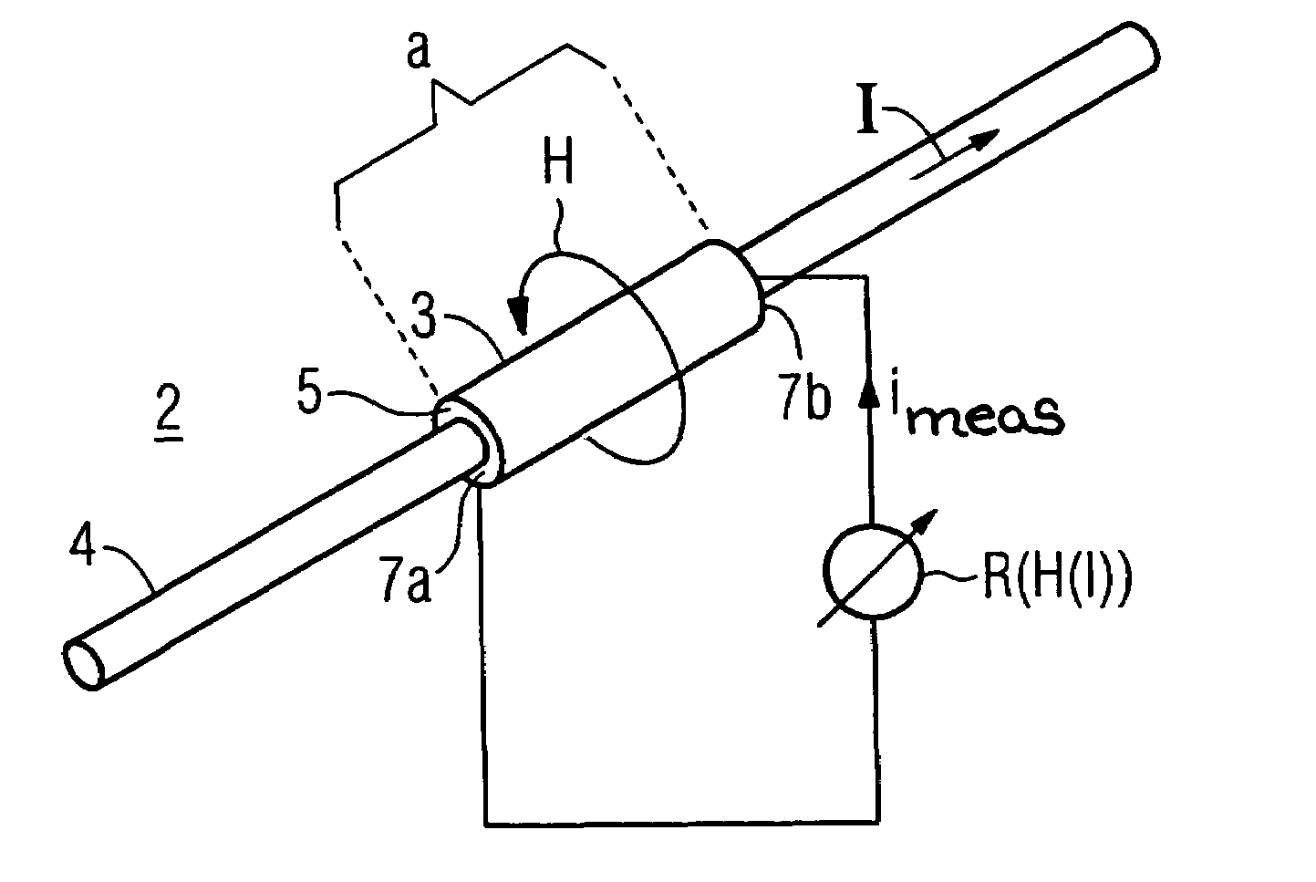
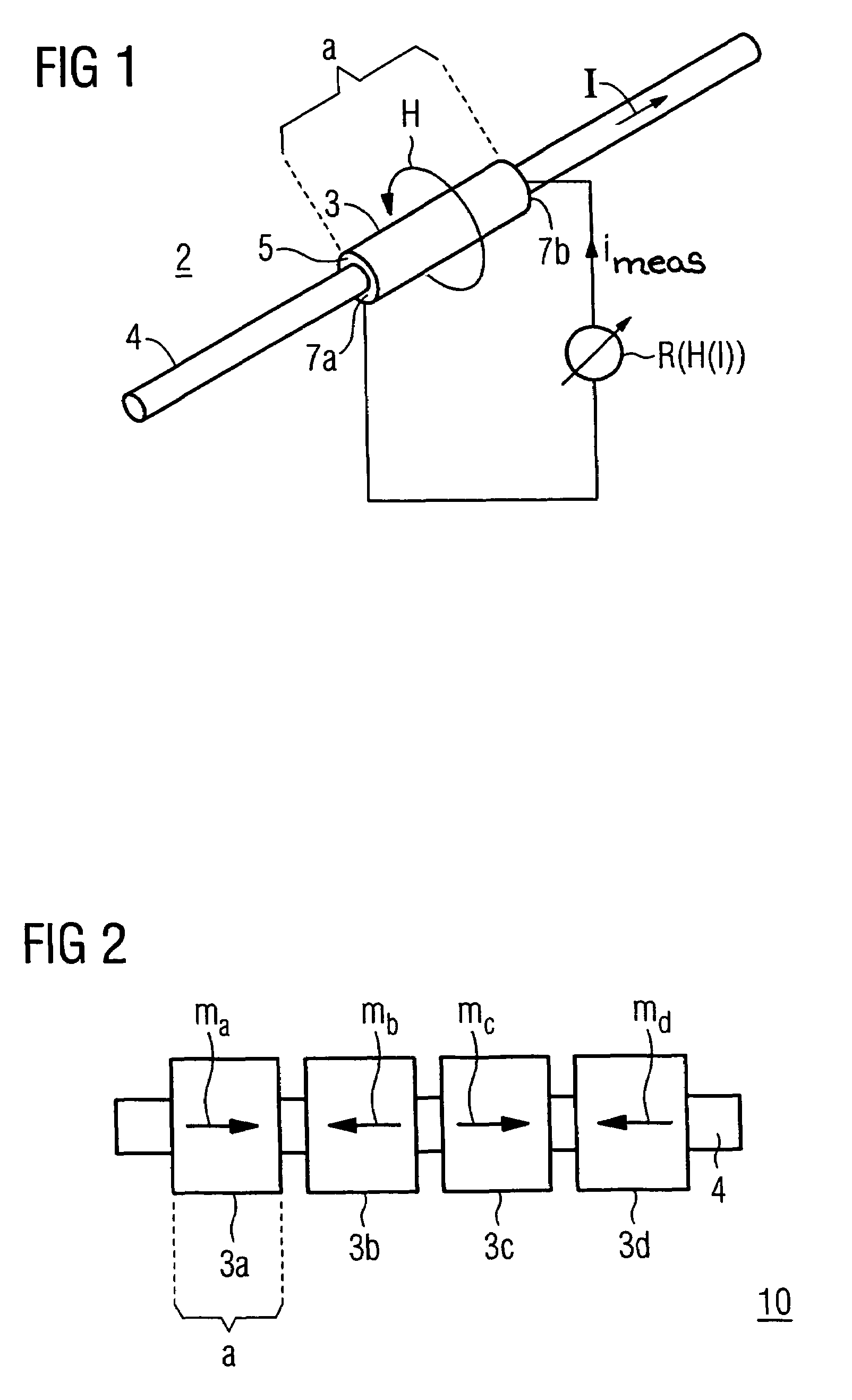
[0028]The current measurement apparatus 2 which is illustrated according to an embodiment of the invention, as illustrated in FIG. 1, has a sensor element 3 which surrounds an electrical conductor 4 through which direct current or alternating current I is flowing. In this case, the sensor element 3 is conductively isolated from the electrical conductor 4, for example being isolated from it by way of a thin insulation layer 5.

[0029]The sensor element is in particular in the form of a ring or sleeve, which represents a sheath which magnetically completely surrounds the electrical conductor 4 in the circumferential direction. In this case, the sensor element has a predetermined extent which is pronounced in the axial direction and shall be at least 1 mm. At least a substantial proportion of it is composed of a magnetoresistive material.

[0030]Fundamentally, all materials which are known per se with an XMR effect (see the cited brochure “XMR Technologies”, pages 11 to 43) may be used for...


PUM


Abstract

The apparatus for measurement of a current which is flowing in an axially elongated electrical conductor at a first electrical potential. The apparatus contains at least one associated sensor element associated with the conductor that is electrically isolated from it at a second electrical potential different from the first electrical potential of the electrical conductor, and having magnetoresistive characteristics. The sensor element is intended to form a loop which is magnetically closed around the conductor in the circumferential direction, with the resistance value being tapped off at axially opposite ends. Its magnetoresistive part is preferably composed of a non-metallic powder composite material with a high magnetoresistive effect.

Description

[0001]The present application hereby claims priority under 35 U.S.C. §119 on German patent application numbers DE 10 2004 014 212.2 filed Mar. 23, 2004 and DE 10 2004 062 474.7 filed on Dec. 23, 2004, the entire contents of which are hereby incorporated herein by reference.FIELD OF THE INVENTION [0002]The invention generally relates to an apparatus for measurement of a conductor current which is flowing in an axially elongated electrical conductor at a first electrical potential. Preferably, it relates to one having at least one sensor element which is associated with the conductor that is electrically isolated from it and has magnetoresistive characteristics, and having a device for tapping off the resistance value, which is dependent on the magnetic field of the current, across the element and for further processing of this value.BACKGROUND OF THE INVENTION [0003]An apparatus for measurement of a conductor current which is flowing in an axially elongated electrical conductor at a ...

Claims


Application Information

Patent Timeline
Patent Type & Authority Patents(United States)
IPC IPC(8): G01R33/09H01L43/00G01R15/20
CPCG01R15/205
Inventor LUDWIG, KLAUSRIEGER, GOTTHARD
Owner SIEMENS AG
Why Eureka
Try Eureka