Light emitting array apparatus and method of manufacture

a technology of light-emitting arrays and display devices, which is applied in the direction of identification means, instruments, landing aids, etc., can solve the problems of large heat generated by leds themselves, large display screens in this form, and inability to easily be mounted to an existing wall or other support structure, so as to reduce the size, bulk or cost of such display devices

Active Publication Date: 2008-02-26
LIGHTHOUSE TECH LTD
View PDF11 Cites 36 Cited by
  • Summary
  • Abstract
  • Description
  • Claims
  • Application Information

AI Technical Summary

Benefits of technology

[0009]It is an object to the present invention to provide a light emitting array apparatus that may be mounted directly to a supporting wall or support surface or may reduce the size, bulk or cost of such display devices. As a minimum, it is an object to the present invention to provide the public with a useful choice.SUMMARY OF THE INVENTION
[0040]providing weather proofing over said electrical circuitry to protect said electrical circuitry from moisture or water directed to a front face thereof.

Problems solved by technology

It is a common problem in the industry that the use of a plurality of LEDs to provide a display generate significant heat from the LEDs themselves.
Such a system requires either access to the external environment from the rear of the screen such as air circulating behind the screen housing or more complicated methods to remove the heat.
Furthermore, display screens in this form are relatively bulky due to the accommodation of fans and cooling systems.
They are also expensive due to the extra elements required and heavier when it comes to transportation or installation of the screens.
A further problem with such screens is that any maintenance or similar problems with the screen need to be dealt with through access panels in the back of the housing requiring access to the back of the panel.
The result of such problems is that display screens are typically constructed as standalone items so that access to both air and maintenance personnel can be maintained to the back of the screen.
They cannot easily be mounted to an existing wall or other support structure without an air gap behind the housing or complex fitting arrangements to allow the screen to be rotated away from the wall or support structure for access to be gained for servicing.
Similar problems with heat may also exist with LED devices used for general lighting, automotive lights, traffic signal lights and other such devices.
Again, a plurality of LEDs in a panel may generate significant heat leading to often-bulky constructions.

Method used


Image

  • Light emitting array apparatus and method of manufacture
  • Light emitting array apparatus and method of manufacture
  • Light emitting array apparatus and method of manufacture

Examples


Embodiment Construction

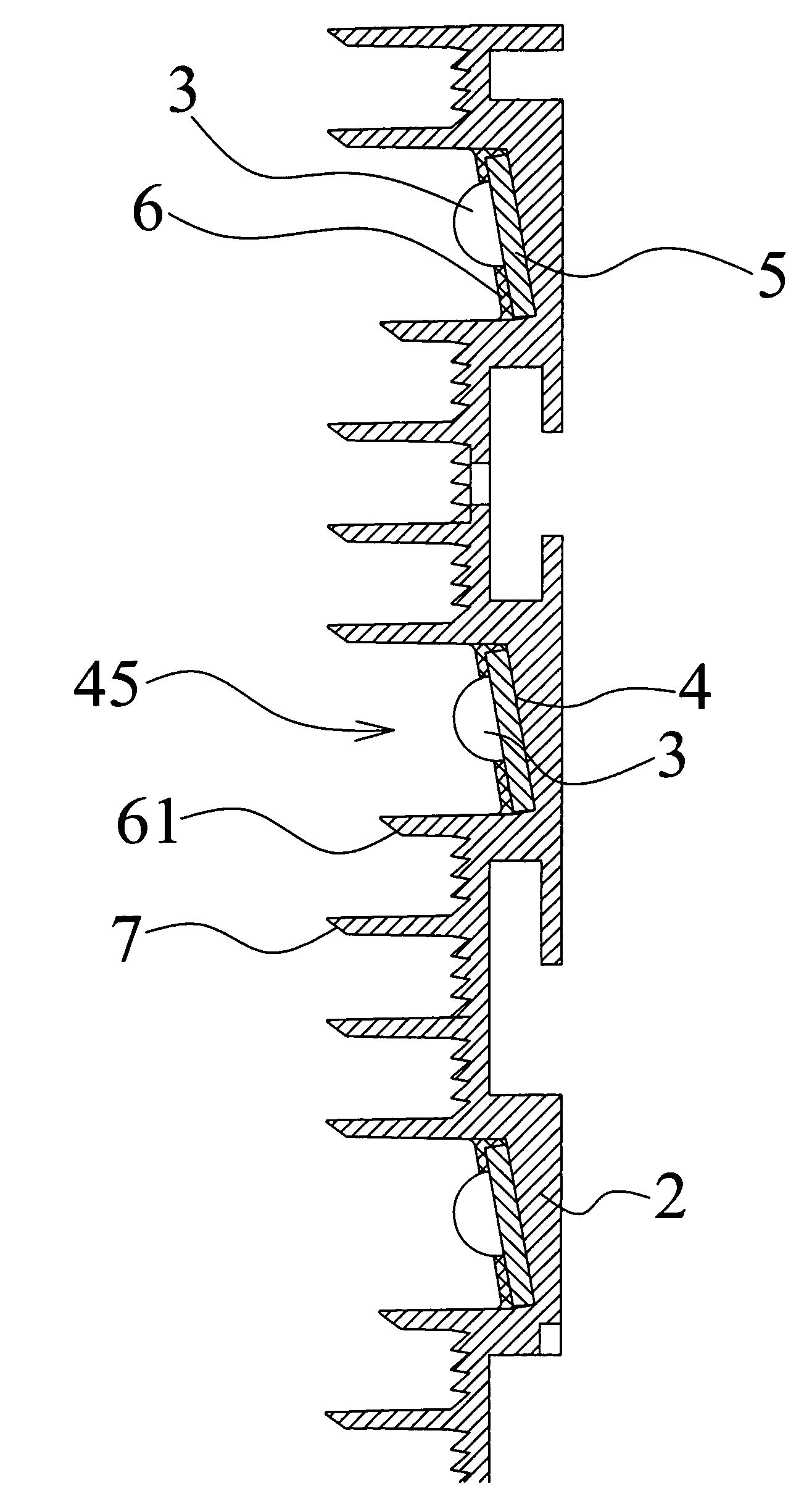
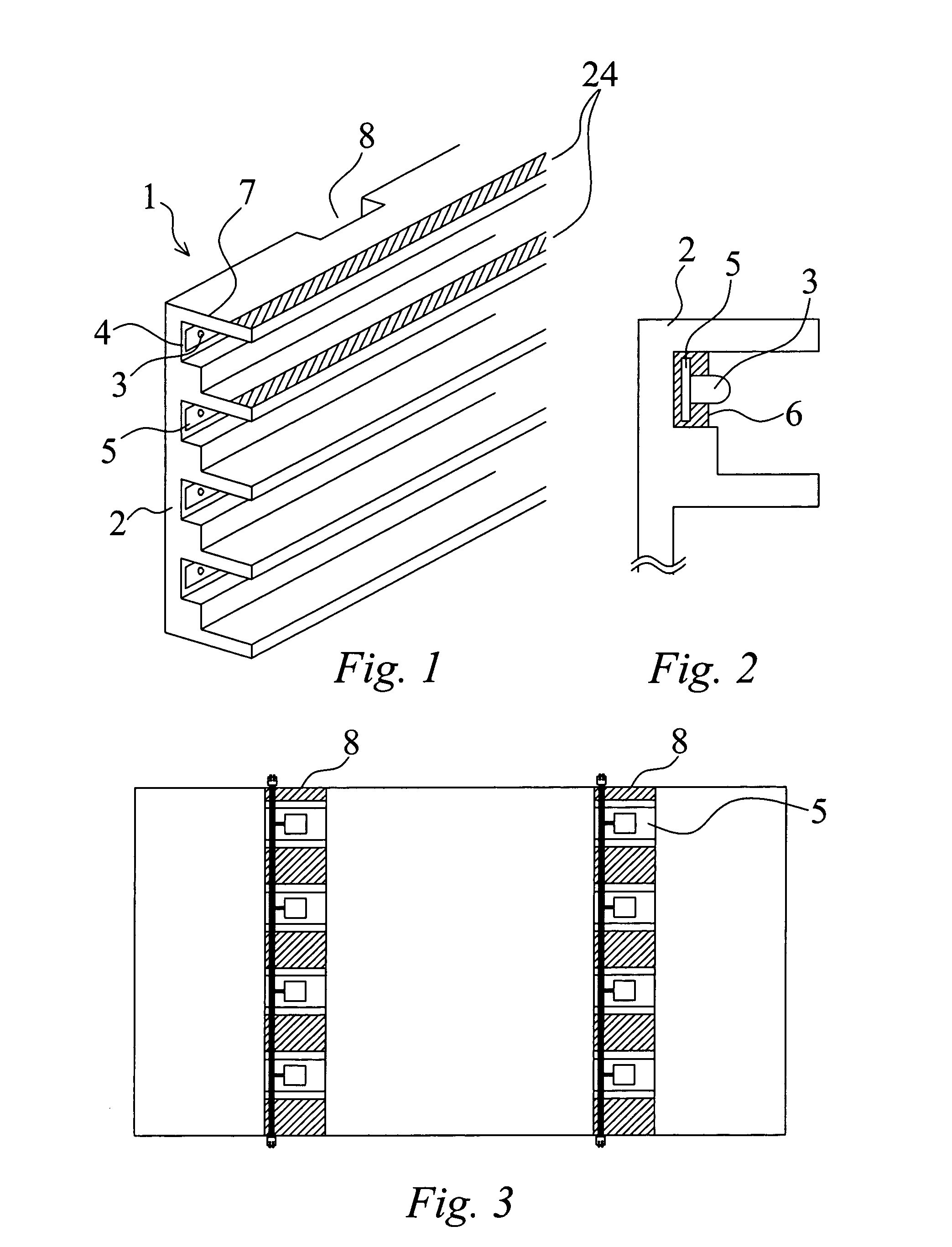
[0052]This invention provides a light emitting array apparatus 1 such as a display device as may be shown in a first embodiment in FIG. 1. It should be noted from the outset that such a panel may be an entire device used in a lighting application or, more likely, a modular unit for use with a plurality of similar panels in the construction of a larger screen display or illuminating device. For this reason, the panel is not intended to describe an entire unit with all data, power or other items, except for those that may be used in a module itself. A variety of associated apparatus may be included in the construction of a large screen as is already well known in the art.

[0053]The display device 1 may include a support panel 2 onto which a plurality of light-emitting devices (LEDs) may be mounted. It is intended that the LEDs 3 may be forward facing and mounted to the front face 4 of the support 2.

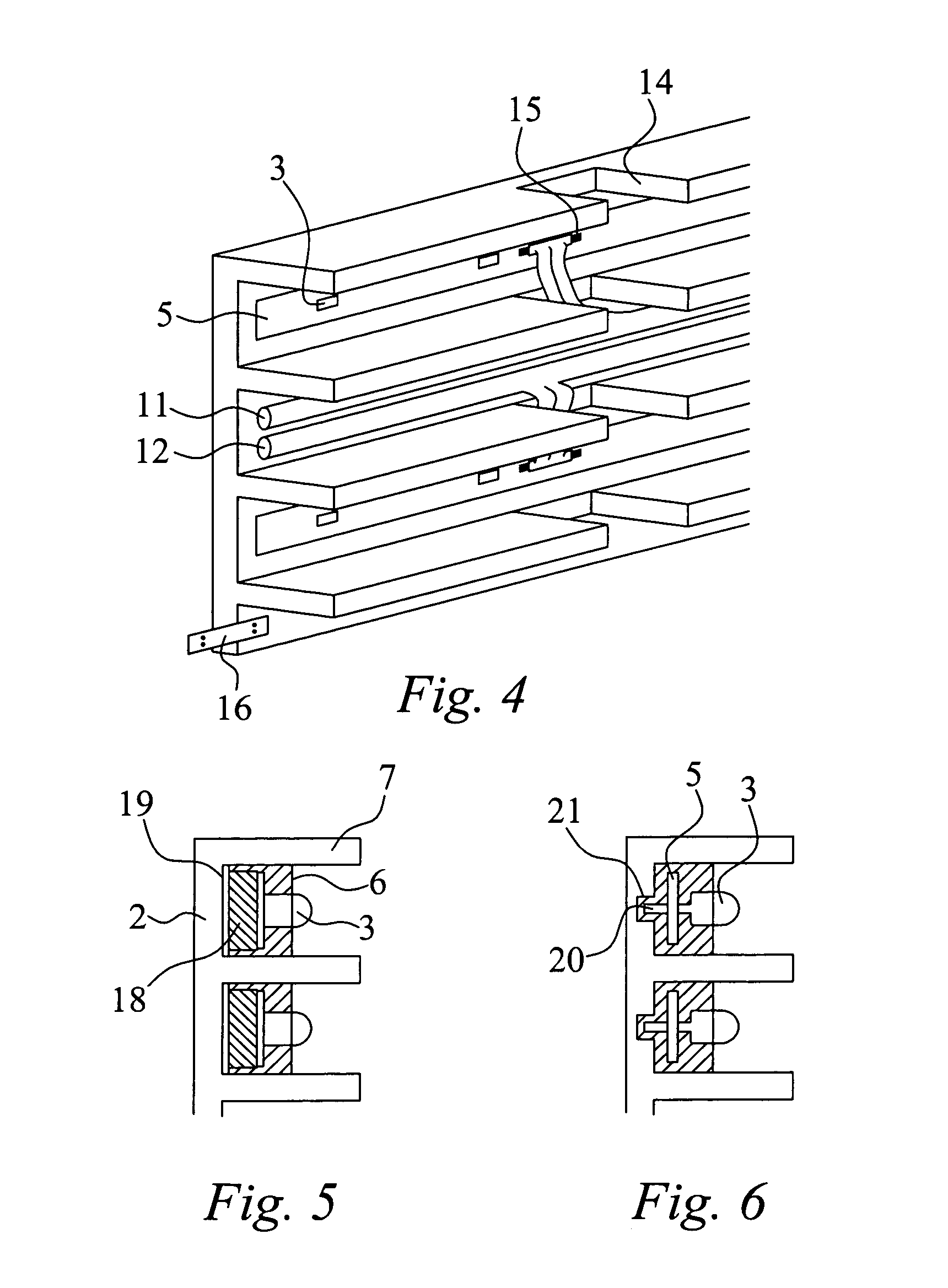
[0054]The LEDs themselves require driving circuitry to supply a current signal appropria...


PUM


Abstract

This invention provides a light emitting array apparatus for use in a video screen display or lighting device incorporating a panel having a plurality of LEDs. Such a panel provides a plurality of LEDs on the front face of the panel in close thermal proximity to the panel. Typically this would include LEDs mounted to a PCB that is then affixed to the panel such that heat may transfer from the LEDs into the support panel itself. The support panel can disperse the heat throughout the panel and the to the surrounding air, especially from the front face of the panel. Such a construction may alleviate the need for fans or other cooling apparatus behind the panel and allow for the panel to be fitted directly to a supporting wall or other structure and also reduce cost and bulk of construction.

Description

FIELD OF THE INVENTION[0001]This invention relates to light emitting array apparatus having a plurality of light emitting diodes (LEDs) such as those for the display of video content as a video screen or billboard for advertising. Other such devices may include panels of LEDs for general illumination, traffic signals, etc.BACKGROUND TO THE INVENTION[0002]A large number of video screens or other display devices utilizing LEDs already exist in the marketplace. The normal method for constructing such display screens is to provide a plurality of LEDs mounted through a printed circuit board (PCB). Driving circuitry for the LEDs may be mounted on further boards or on the reverse side of the PCB to which the LEDs are mounted.[0003]The PCB and LED combination are then typically mounted into a box such that the LEDs may protrude through holes in a front screen to display to the front of the display or be enclosed behind a transparent cover or lens.[0004]It is a common problem in the industry...

Claims


Application Information

Patent Timeline
Patent Type & Authority Patents(United States)
IPC IPC(8): G08B5/22
CPCF21S48/328F21V11/02F21V29/76G09F9/33F21V29/75F21V29/004F21S4/003F21V27/00F21Y2101/02F21S4/20F21Y2115/10
Inventor VAN DE VEN, ANTONY
Owner LIGHTHOUSE TECH LTD
Why Eureka
Try Eureka