High-definition pixel structure of electrochromic displays and method of producing the same

a high-definition, electrochromic technology, applied in the field of display, can solve the problems of blurred pixel borders, display structure difficulty for high-resolution displays, etc., and achieve the effect of reducing the thickness of the layer containing electrochromic materials

Active Publication Date: 2008-02-26
JAPAN DISPLAY INC +1
View PDF5 Cites 2 Cited by
  • Summary
  • Abstract
  • Description
  • Claims
  • Application Information

AI Technical Summary

Benefits of technology

[0010]Here, a metal used as a pixel electrode has high intensity reflectance and reflects light incident on a display, so that the display can provide a necessary quantity of reflection light even when having the thickness of an electrochromic material thinned and scattered light reduced. On the other hand, when a boundary between the electrochromic material and a part in a transparent electrode, onto which a current from a pixel electrode is concentrated, is colored, the reflected light from the pixel electrode is shielded. Particularly, when employing a metal having high intensity reflectance for the pixel electrode, the display acquires a high reflectance which is a ratio of the quantity of the light incident on a display to the quantity of the reflected light.
[0011]The present invention can provide a display which has the thickness of a layer containing an electrochromic material reduced, and a method of producing the same.

Problems solved by technology

As a result, the display has structural difficulty for a high-resolution display, due to a problem that when the display tries to produce such a high-resolution display as to give a pixel pitch equal distance to the thickness of the white layer, a pixel border becomes blurred, because an aspect ratio of the pixel pitch to the thickness is insufficient.

Method used


Image

  • High-definition pixel structure of electrochromic displays and method of producing the same
  • High-definition pixel structure of electrochromic displays and method of producing the same
  • High-definition pixel structure of electrochromic displays and method of producing the same

Examples


first embodiment

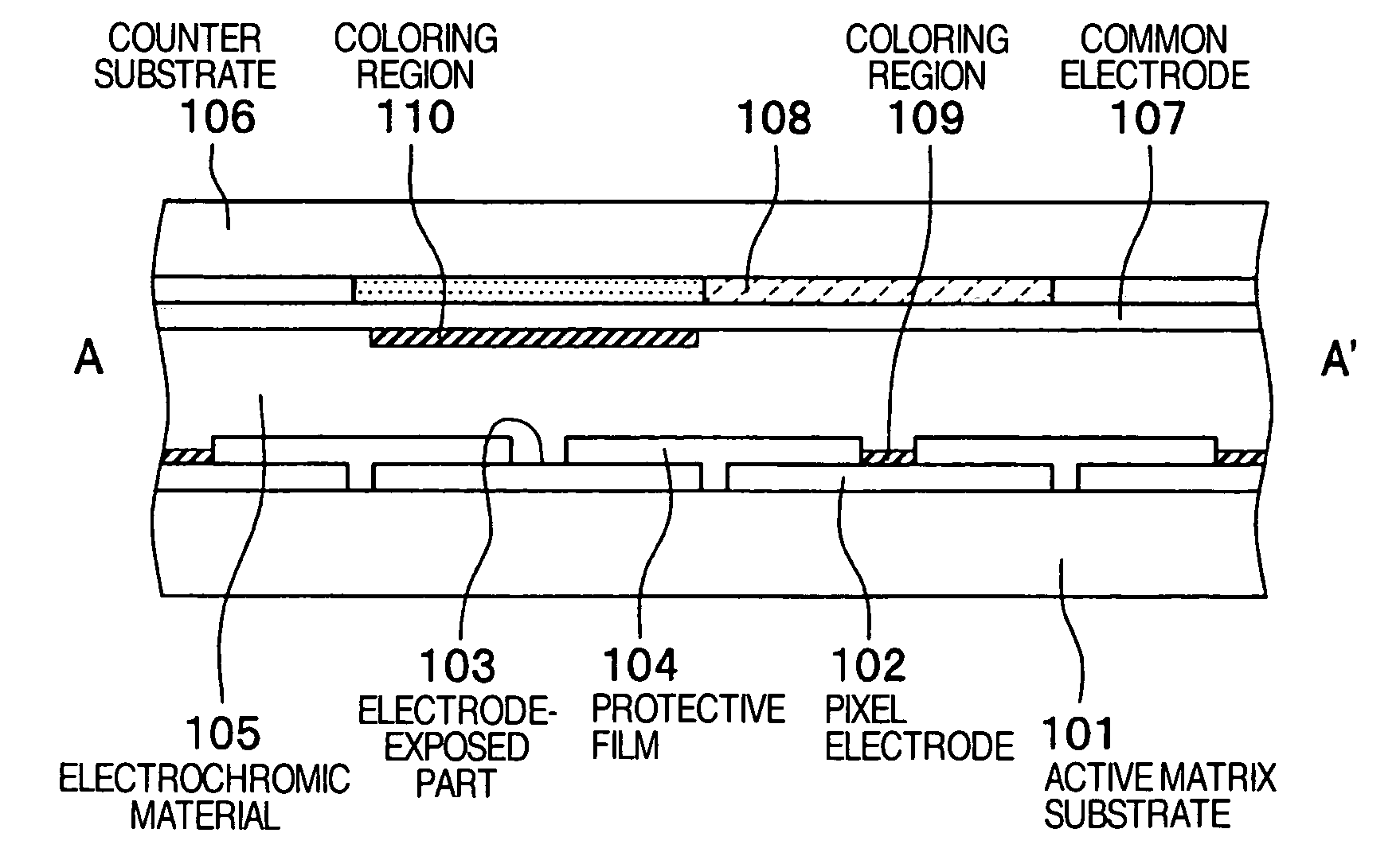
[0019]In the next place, a display according to the present embodiment will be described with reference to FIGS. 1A and 1B.

[0020]FIG. 1A shows a plan view of the display according to the present embodiment, and FIG. 1B shows a sectional view of A-A′ in FIG. 1A. The display according to the present embodiment is mainly composed of: an active matrix substrate 101 having pixels formed in a matrix form in a row direction and a column direction; a transparent counter substrate 106 which faces to the active matrix substrate 101 of a back substrate in parallel; and an electrochromic material 105 which is sandwiched by the active matrix substrate 101 and the counter substrate 106. By the way, in the following discussion, “top and bottom” is an expression with reference to the drawings, so that top and bottom are reversed or shown in right and left, depending on a way of representation of the drawing.

[0021]On an active matrix substrate 101, a plurality of pixel electrodes 102 with a rectangu...

second embodiment

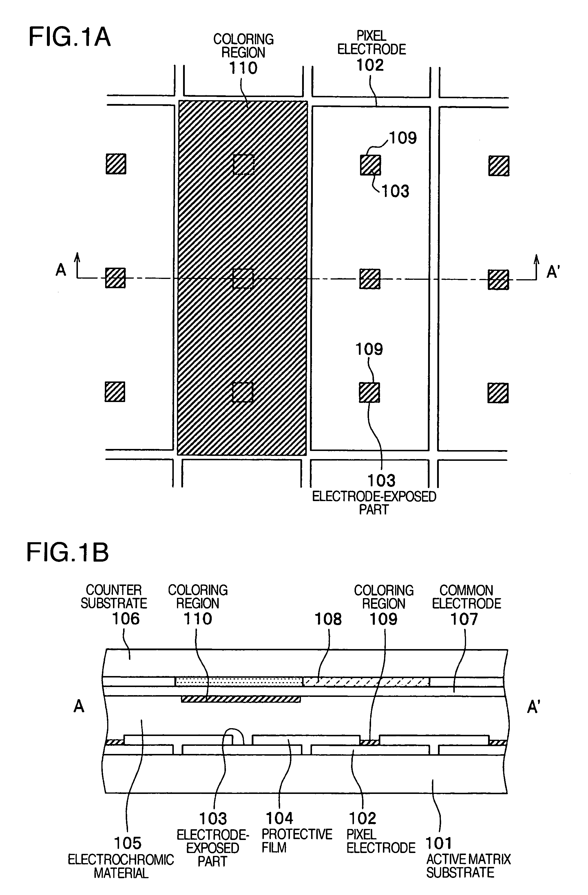
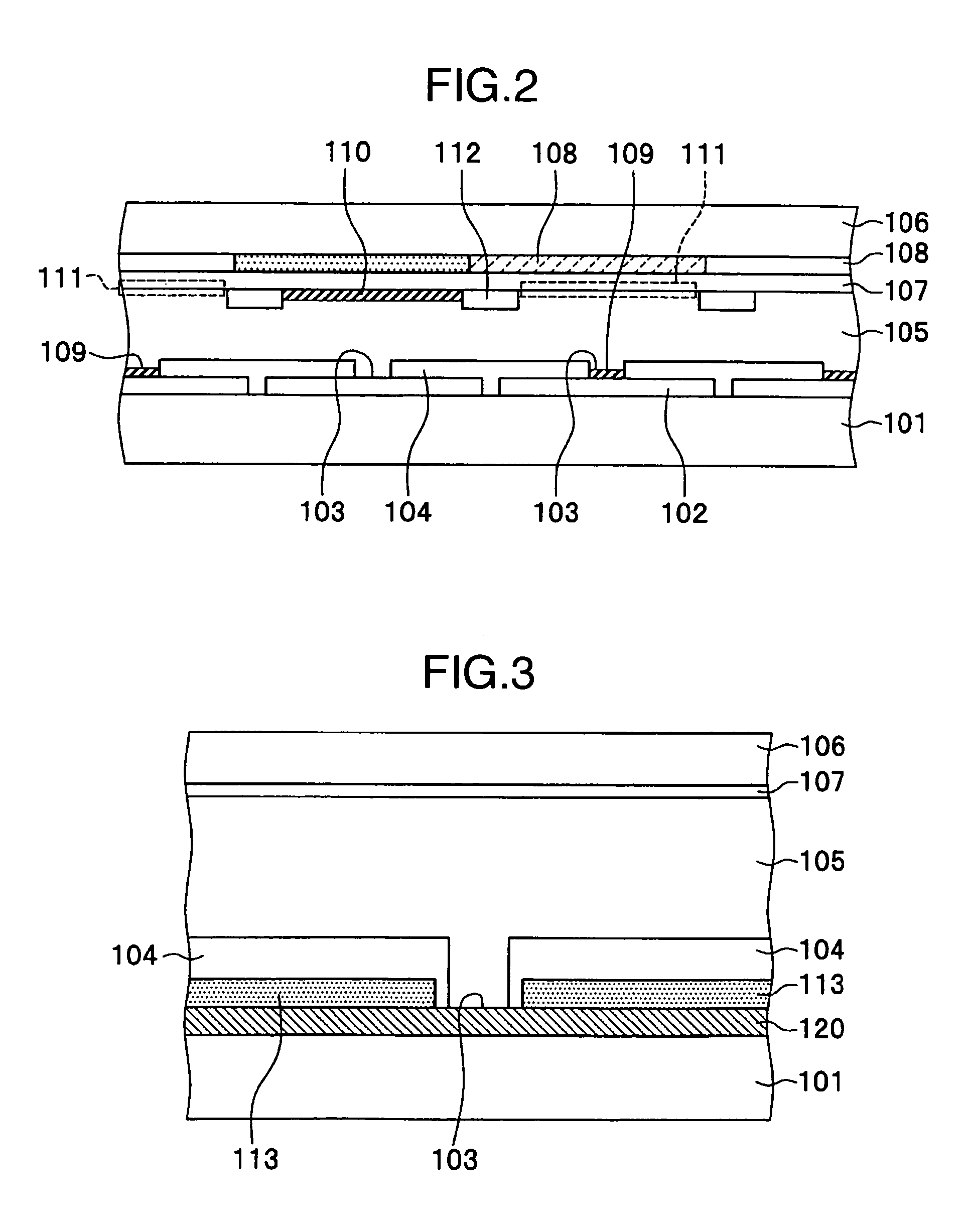
[0030]The first embodiment employs a metal with a high intensity reflectance of light for a pixel electrode 102, and employs a protective film 104 for covering a part other than an electrode-exposed part 103; but it is possible to employ a metal with a low light intensity reflectance but high corrosion resistance (corrosiveness), form a contacting layer made from the metal on an active matrix substrate 101, layer a metal having a high intensity reflectance as a reflecting electrode on the contacting layer, and layer a protective film 104 on the surface of the reflecting electrode so as to protect it from corroding due to an electrochromic material 105. In the next place, the configuration will be described as a second embodiment. As for a part common to the first embodiment, the same reference numeral will be attached and the description will be omitted.

[0031]FIG. 3 shows a sectional view of a display in a second embodiment.

[0032]An electrode-exposed part 103 according to the presen...

third embodiment

[0034]In the first embodiment, one part of a pixel electrode 102 is forced to contact with an electrochromic material 105 as an electrode-exposed part 103, but it is possible to avoid the pixel electrode from directly contacting with the electrochromic medium, by using electroless plating. In the next place, the above configuration will be described as a third embodiment. In the third embodiment, a part common to the first embodiment will be marked with the same reference numeral, and the description will be omitted.

[0035]FIG. 4 shows a sectional view of a display of the third embodiment. A contacting layer 121 is deposited at an electrode-exposed part 103 on an active matrix substrate 101 with an electroless plating process. In addition, a protective film 104 is formed on the other part than the electrode-exposed part 103. It is recommended to select a material which forms the contacting layer 121 from materials which hardly cause a problem of corrosion caused by an electrochromic ...


PUM

PropertyMeasurementUnit
electrochromicaaaaaaaaaa
areaaaaaaaaaaa
light-intensity reflectanceaaaaaaaaaa

Abstract

A display of an electrochromic type, including an active matrix substrate on which a plurality of pixel electrodes corresponding to pixels are arranged in a matrix form; a counter substrate which is provided with a transparent electrode that is common with respect to a plurality of the pixel electrodes; and an electrochromic material which is sandwiched between the active matrix substrate and the counter substrate, and is colored in a boundary either between itself and the pixel electrode or between itself and the transparent electrode; wherein the pixel electrode other than an electrode-exposed part which contacts with the electrochromic material is covered with a transparent protective film; and the electrode-exposed part has a different area from the area of the part onto which a current generated between the transparent electrode and the pixel electrode concentrates, out of the transparent electrode.

Description

BACKGROUND OF THE INVENTION[0001](1) Field of the Invention[0002]The present invention relates to a display of a matrix type using an electrochromic material, and a method of producing the same.[0003](2) Description of Related Art[0004]An electrochromic material means a coloring substance which precipitates, dissolves, discolors or colors caused by an electrochemical oxidation or reduction reaction, and a matrix type display using the material is disclosed (JP-A-2002-258327). The display has the coloring substance of the electrochromic material and an electrolyte provided between a transparent electrode on an observer side and a metallic electrode on a substrate side, in every pixel; produces a dark display by making the coloring substance at the transparent electrode into a coloring state; and produces a light display by making the coloring substance into a colorless state and consequently making white particles in the electrolyte reflect light (scattered light).SUMMARY OF THE INVE...

Claims


Application Information

Patent Timeline
Patent Type & Authority Patents(United States)
IPC IPC(8): G02F1/153G09G3/19G09G3/38
CPCG02F1/157G02F1/133512G02F1/133514G02F2001/1536
Inventor HIROTA, SHOICHIOHSHIMA, TETSUYASUGITA, TATSUYA
Owner JAPAN DISPLAY INC
Why Eureka
Try Eureka