State-based jitter buffer and method of operation

a buffer and state-based technology, applied in the field of jitter buffer, can solve problems such as packet loss, packet delay, packets of a packet stream to be delayed, and affect the quality of audio streams

Inactive Publication Date: 2008-02-26
INTEL CORP
View PDF16 Cites 26 Cited by
  • Summary
  • Abstract
  • Description
  • Claims
  • Application Information

AI Technical Summary

Problems solved by technology

A number of factors can affect the quality of the audio stream, including packet loss, packet delay, and packet jitter.
Packet loss may result from packet collisions or network overload, and variable routing paths may cause some packets of a packet stream to be delayed relative to other packets in that stream.
Packet losses and delays—both of which are typically beyond the control of the receiver—may result in a stream of packets being received out of order and at a non

Method used


Image

  • State-based jitter buffer and method of operation
  • State-based jitter buffer and method of operation
  • State-based jitter buffer and method of operation

Examples


Embodiment Construction

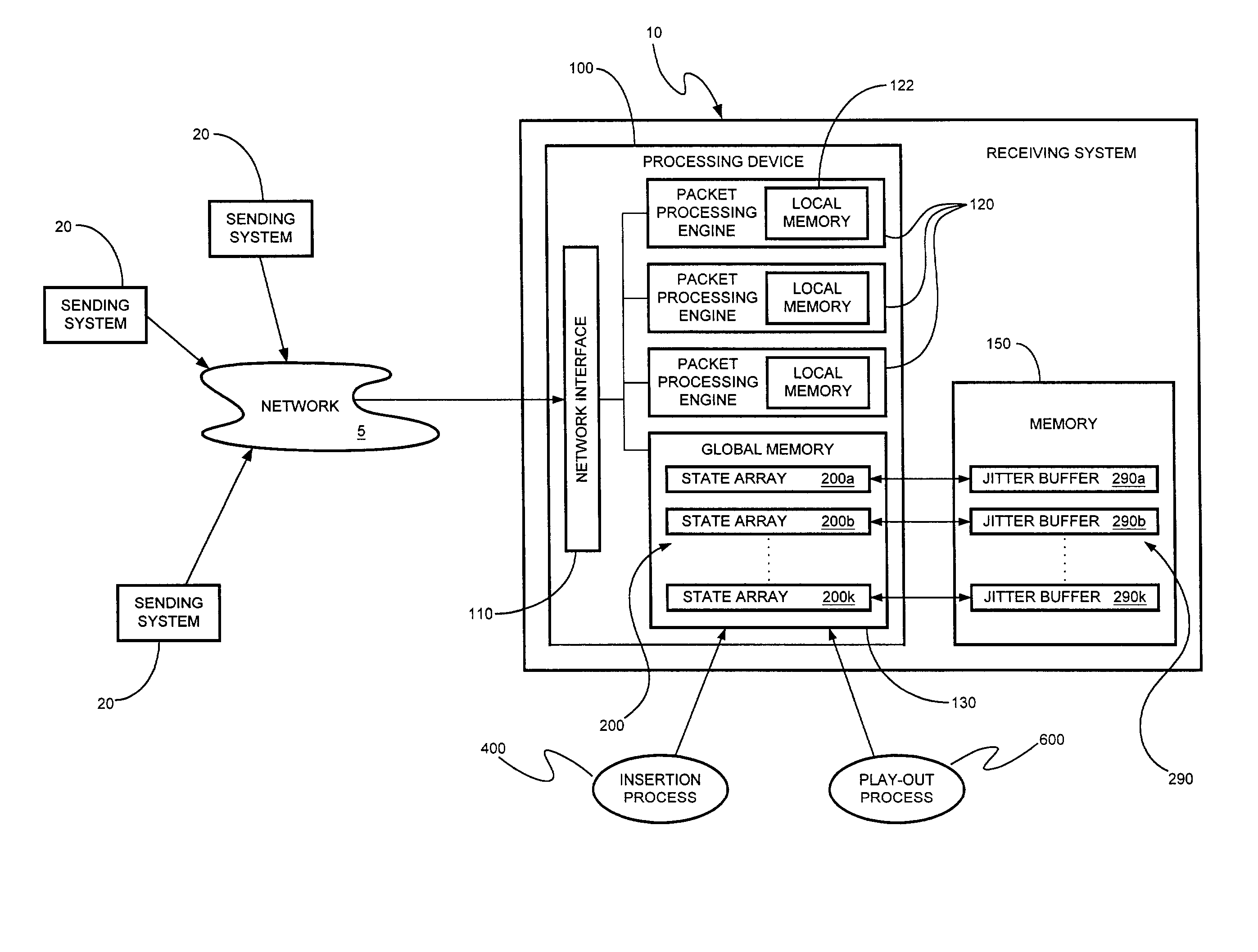
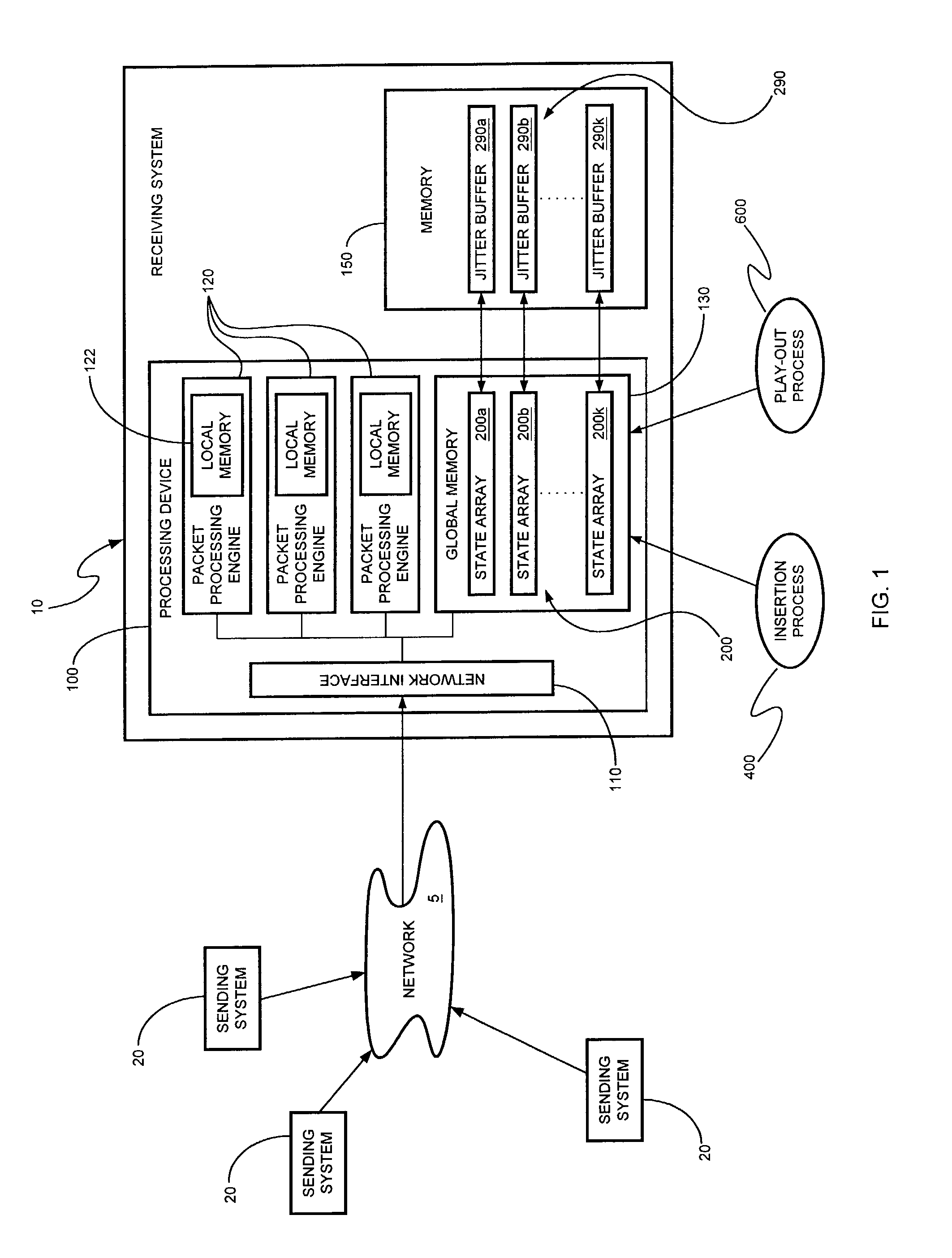
[0014]Referring to FIG. 1, an exemplary embodiment of a receiving system 10 is illustrated. The receiving system 10 is coupled with a network 5. The network 5 may, in turn, be coupled with one or more sending systems 20, each sending system 20 comprising any addressable device or node coupled with the network 5. The network 5 may comprise any type of network, including the Internet, a wide area network (WAN), a metropolitan area network (MAN), a local area network (LAN), or a system area network (SAN), that exhibits any suitable network architecture.

[0015]A sending system 20 may send a message comprising a stream of packets (e.g., an audio and / or video message) to the receiving system 10. The packetized message may conform with a set of specifications or protocol, such as the Real-Time Transport Protocol, as noted above. The packets making up a message transmitted by one of the sending systems 20 may travel a number of different paths across the network 5 to reach the receiving syst...


PUM


Abstract

A buffer having an associated state array to store the current state of the buffer. The state array includes a bit array having a number of entries, each of the entries including a status bit to indicate storage of a corresponding packet in the buffer.

Description

FIELD[0001]Embodiments of the invention relate generally to the transmission of packets over a network and, more particularly, to a jitter buffer having an associated state array.BACKGROUND[0002]In voice-over-packet telephony, an audio conversation is transmitted over a network as a stream of packets. A number of factors can affect the quality of the audio stream, including packet loss, packet delay, and packet jitter. Packet loss may result from packet collisions or network overload, and variable routing paths may cause some packets of a packet stream to be delayed relative to other packets in that stream. Packet losses and delays—both of which are typically beyond the control of the receiver—may result in a stream of packets being received out of order and at a non-constant rate, thereby causing packet jitter. A stream of audio (and / or video) packets must, however, be played out in the correct order and at a constant rate in order to reconstruct the original message.[0003]To assis...

Claims


Application Information

Patent Timeline
IPC IPC(8): H04L12/54H04L12/56H04L12/64
CPCH04L49/90H04L49/901H04L2012/6489H04L49/9023
Inventor VINNAKOTA, BAPIRAJUMOHAMMADALI, SALEEMGILBERT, DAVID W.
Owner INTEL CORP
Why Eureka
Try Eureka