Audio coding system using characteristics of a decoded signal to adapt synthesized spectral components

a spectral component and audio coding technology, applied in the field of audio coding systems, can solve the problems of not working well in all situations, not providing very good audio quality, and not working as well in lower bit rate systems, and achieve the effect of improving the perceived quality of audio signals

Active Publication Date: 2008-02-26
DOLBY LAB LICENSING CORP
View PDF32 Cites 43 Cited by
  • Summary
  • Abstract
  • Description
  • Claims
  • Application Information

AI Technical Summary

Benefits of technology

[0012]It is an object of the present invention to provide techniques that can be used in low bit rate audio coding systems to improve the perceived quality of the audio signals generated by such systems.

Problems solved by technology

Traditional perceptual coding techniques work reasonably well in audio coding systems that are allowed to transmit or record encoded signals having medium to high bit rates, but these techniques by themselves do not provide very good audio quality when the encoded signals are constrained to low bit rates.
Techniques like HFR and SHF can provide an advantage in many situations but they do not work well in all situations.
One situation that is particularly troublesome arises when an audio signal having a rapidly changing amplitude is encoded by a system that uses block transforms to implement the analysis and synthesis filterbanks.
This technique works well in audio coding systems that are allowed to transmit or record encoded signals having medium to high bit rates, but it does not work as well in lower bit rate systems because the use of shorter blocks reduces the coding gain achieved by the transform.
Unfortunately, this technique obscures the true spectral characteristics of the input signal, thereby distorting information needed for effective perceptual coding, and because the transmitter must use part of the transmitted signal to convey parameters that the receiver needs to reverse the effects of the modifications.
This technique is undesirable in low bit rate systems because of the signal overhead needed to convey the predictive filter coefficients.

Method used


Image

  • Audio coding system using characteristics of a decoded signal to adapt synthesized spectral components
  • Audio coding system using characteristics of a decoded signal to adapt synthesized spectral components
  • Audio coding system using characteristics of a decoded signal to adapt synthesized spectral components

Examples


Embodiment Construction

A. Overview

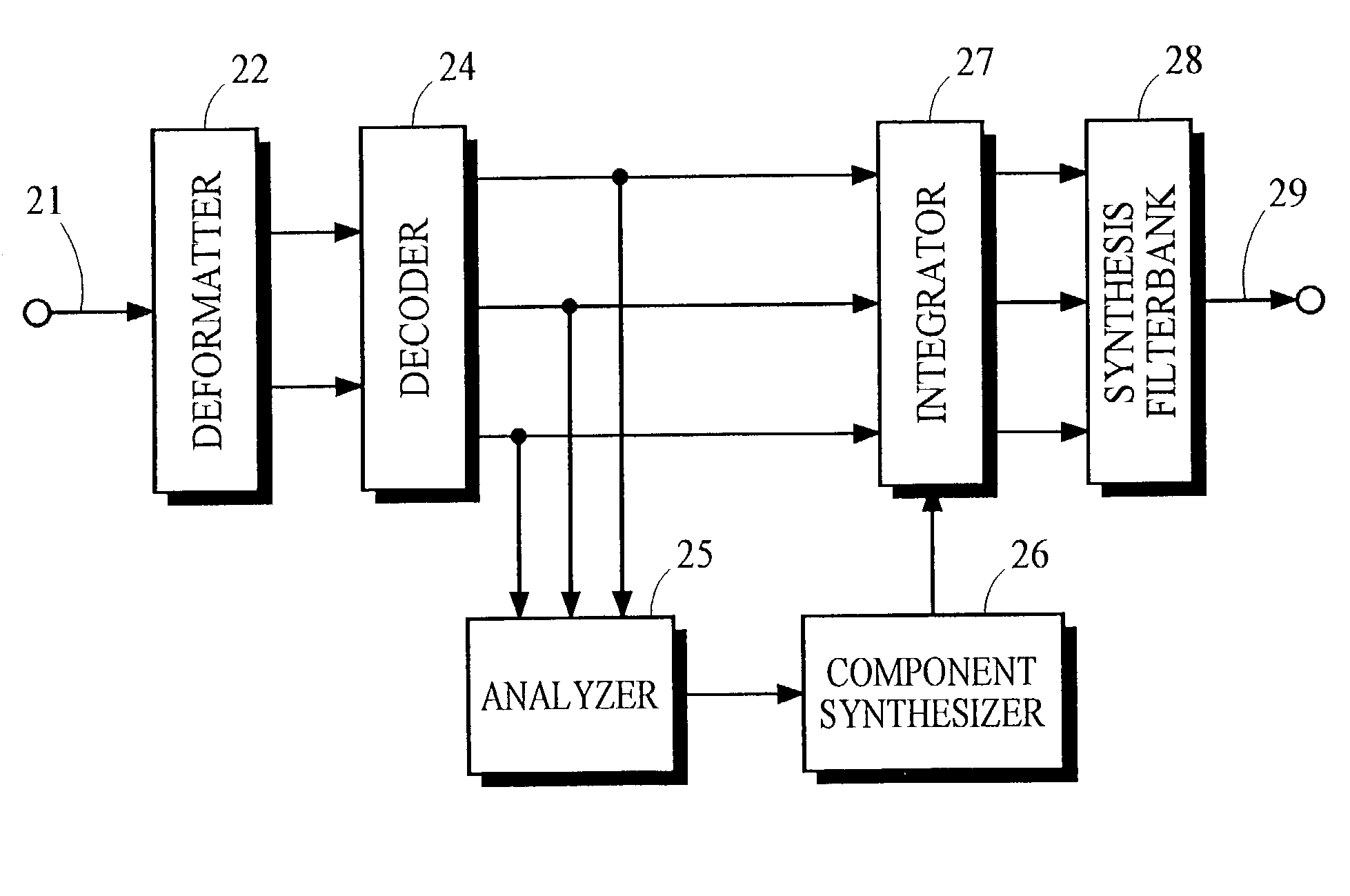
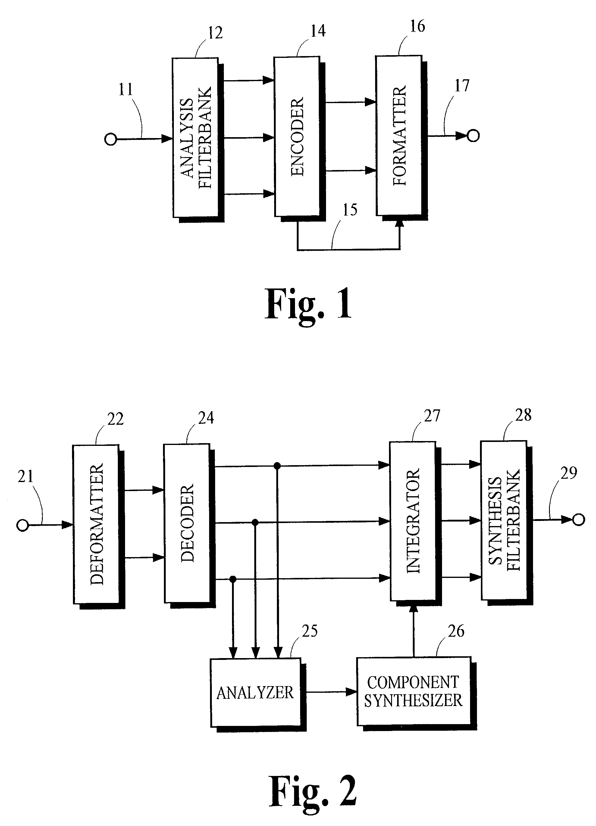
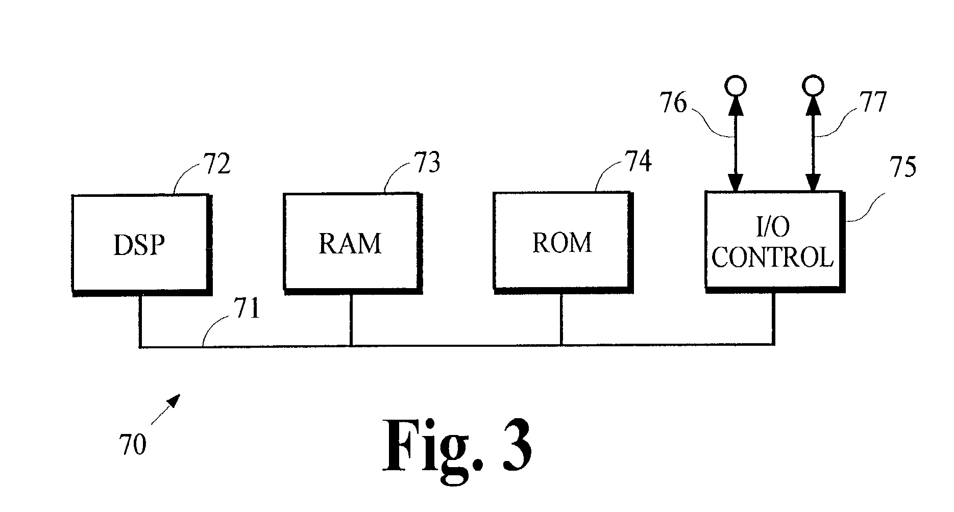
[0018]Various aspects of the present invention may be incorporated into a variety of signal processing methods and devices including devices like those illustrated in FIGS. 1 and 2. Some aspects may be carried out by processing performed in only a receiver. Other aspects require cooperative processing performed in both a receiver and a transmitter. A description of processes that may be used to carry out these various aspects of the present invention is provided below following an overview of typical devices that may be used to perform these processes.

[0019]FIG. 1 illustrates one implementation of a split-band audio transmitter in which the analysis filterbank 12 receives from the path 11 audio information representing an audio signal and, in response, provides frequency subband signals that represent spectral content of the audio signal. Each subband signal is passed to the encoder 14, which generates an encoded representation of the subband signals and passes the encode...


PUM


Abstract

A receiver in an audio coding system receives a signal conveying frequency subband signals representing an audio signal. The subband signals are examined to assess one or more characteristics of the audio signal. Spectral components are synthesized having the assessed characteristics. The synthesized spectral components are integrated with the subband signals and passed through a synthesis filterbank to generate an output signal. In one implementation, the assessed characteristic is temporal shape and noise-like spectral components are synthesized having the temporal shape of the audio signal.

Description

CROSS-REFERENCE TO RELATED APPLICATION[0001]This application is a continuation-in-part of U.S. patent application Ser. No. 10 / 174,493 filed Jun. 17, 2002, and is related to U.S. patent application Ser. No. 10 / 113,858 filed Mar. 28, 2002.TECHNICAL FIELD[0002]The present invention is related generally to audio coding systems, and is related more specifically to improving the perceived quality of the audio signals obtained from audio coding systems.BACKGROUND ART[0003]Audio coding systems are used to encode an audio signal into an encoded signal that is suitable for transmission or storage, and then subsequently receive or retrieve the encoded signal and decode it to obtain a version of the original audio signal for playback. Perceptual audio coding systems attempt to encode an audio signal into an encoded signal that has lower information capacity requirements than the original audio signal, and then subsequently decode the encoded signal to provide an output that is perceptually indi...

Claims


Application Information

Patent Timeline
Patent Type & Authority Patents(United States)
IPC IPC(8): G10L19/00G10L19/02G10L19/028G10L21/02H03M7/30
CPCG10L21/038G10L19/035G10L21/02G10L19/02
Inventor DAVIDSON, GRANT ALLENTRUMAN, MICHAEL MEADFELLERS, MATTHEW CONRADVINTON, MARK STUART
Owner DOLBY LAB LICENSING CORP
Why Eureka
Try Eureka