Knuckle arm

a technology of knuckle and knuckle, which is applied in the field of knuckle arms, can solve the problems of high manufacturing cost and further increase of knuckle arms b>10/b>, and achieve the effects of simple knuckle arms, low cost, and resistance to pivoting

Inactive Publication Date: 2008-03-04
ASIA OPTICAL CO INC
View PDF16 Cites 16 Cited by
  • Summary
  • Abstract
  • Description
  • Claims
  • Application Information

AI Technical Summary

Benefits of technology

[0009]An object of this invention is to provide a knuckle arm that has a simple structure so as to reduce manufacturing costs.
[0015]The friction assembly includes a frictional block connected fixedly to the base and having a frictional surface, and a frictional rod extending through the guide slots in the pivot plates of the base and the through holes in the wing plates of the pivot seat. The frictional rod is movable to press against the frictional surface of the frictional block so as to impart a resistance to pivoting of the pivot seat and the top cover. This maintains the top cover at any position. As such, the structure of the knuckle arm is simple, and therefore can be made at a low cost.

Problems solved by technology

This results in high manufacturing costs.(2) The cam surfaces 131, 141 of the bottom and top cam sliding seats 13, 14 must be made highly precise.
Thus, the manufacturing costs of the knuckle arm 10 are further increased.

Method used


Image

  • Knuckle arm
  • Knuckle arm
  • Knuckle arm

Examples


Embodiment Construction

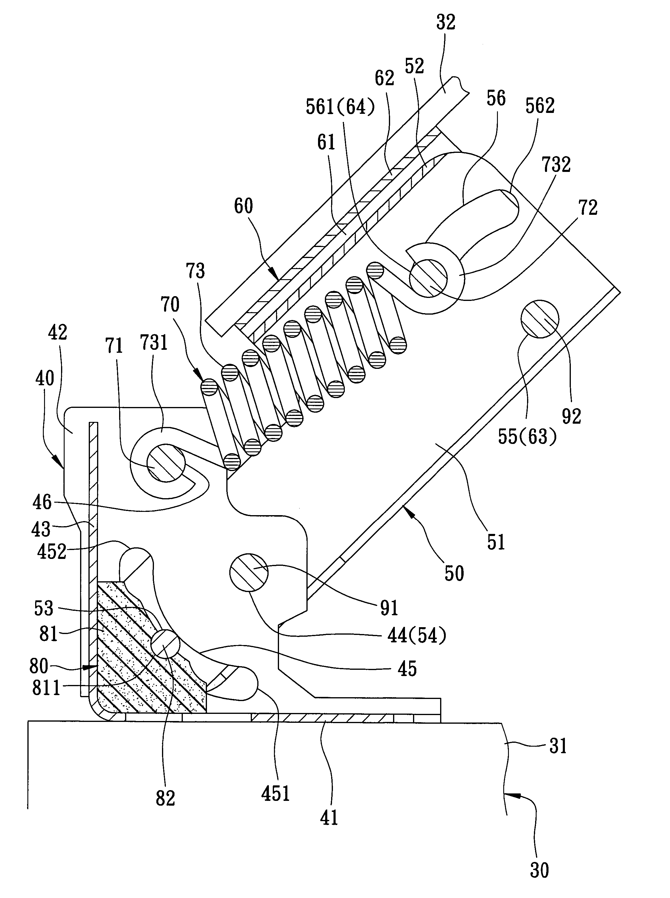
[0028]Referring to FIGS. 2 and 9, the preferred embodiment of a knuckle arm according to this invention interconnects a machine body 31 and a top cover 32 of an office machine 30, and is constructed so as to allow for the opening and closing of the top cover 32 relative to the machine body 31. The office machine may be a copier, scanner, etc.

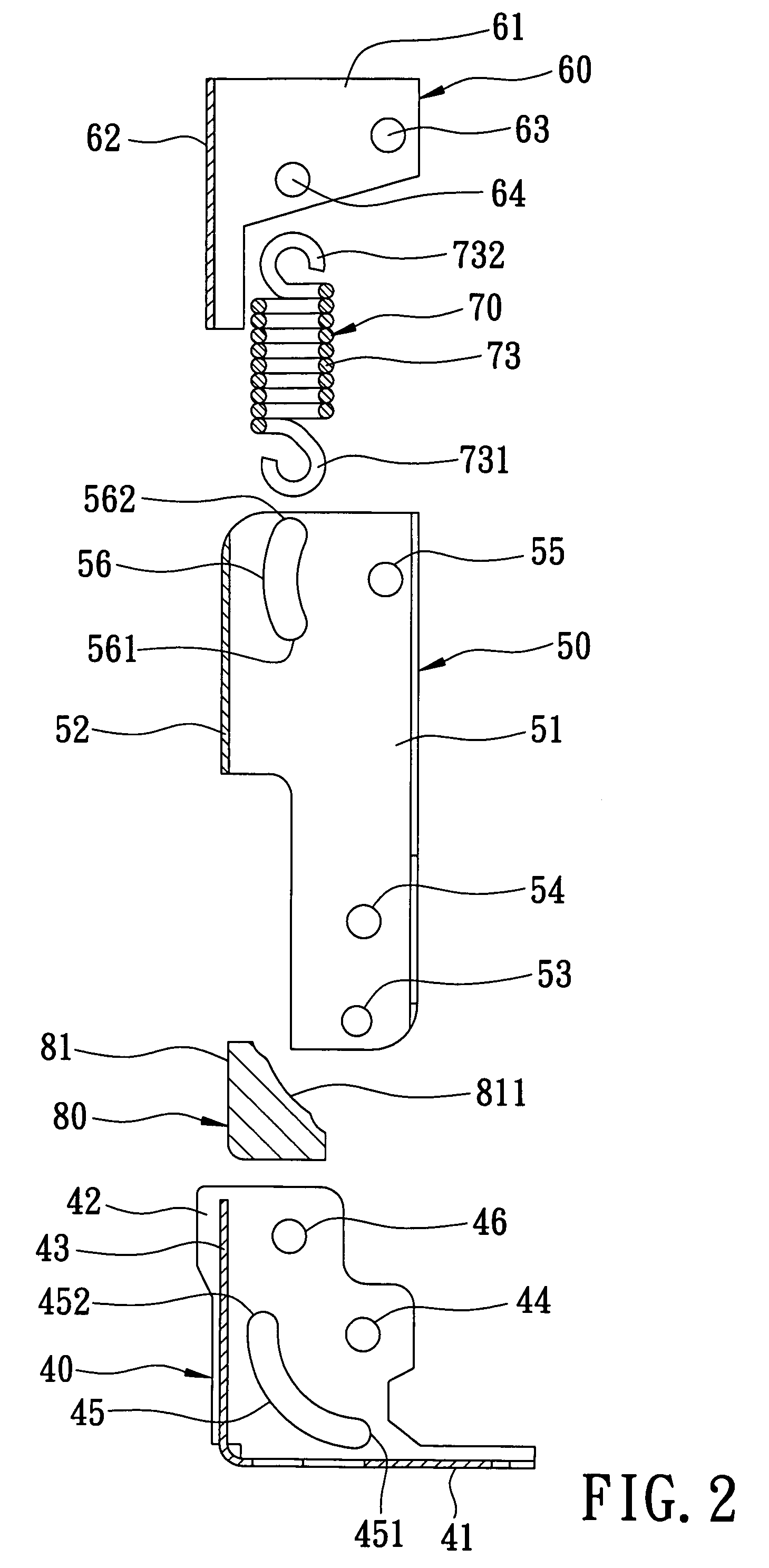
[0029]The knuckle arm includes a base 40, a pivot seat 50 connected rotatably to the base 40 by a first pivot rod 91, a connecting seat 60 connected rotatably to the pivot seat 50 by a second pivot rod 92, a biasing unit 70 disposed between the base 40 and the pivot seat 50, and a friction assembly 80 disposed between the base 40 and the pivot seat 50.

[0030]Referring to FIGS. 2 and 3, the base 40 includes a mounting plate 41 disposed fixedly on the machine body 31, as shown in FIG. 7, two pivot plates 42 extending respectively, integrally, and perpendicularly from two opposite sides of the mounting plate 41, and a connecting plate 43 extending f...


PUM


Abstract

A knuckle arm interconnects a machine body and a top cover of a machine, and includes a base fixed on the machine body, and a pivot seat connected pivotally to the base and attached to the top cover. A biasing unit is disposed between the base and the pivot seat so as to bias the top cover to pivot upwardly. A friction assembly imparts a resistance to pivoting of the top cover so as to maintain the top cover at any position.

Description

CROSS-REFERENCE TO RELATED APPLICATION[0001]This application claims priority of Taiwanese Application No. 093135981, filed on Nov. 23, 2004.BACKGROUND OF THE INVENTION[0002]1. Field of the Invention[0003]This invention relates to a part of an office machine, and more particularly to a knuckle arm that interconnects a machine body and a top cover of an office machine.[0004]2. Description of the Related Art[0005]Two knuckle arms are typically disposed between a top cover and a machine body of an office machine, such as a copier or scanner, for use in the opening and closing of the top cover relative to the machine body. Referring to FIG. 1, a conventional knuckle arm 10, which is disclosed in U.S. Pat. No. 6,456,365, is shown to include a mounting seat 11 fixed on a machine body 21 of an office machine 20, a connecting seat 12 disposed pivotally on the mounting seat 11, a bottom cam sliding seat 13 disposed slidably within the connecting seat 12, a top cam sliding seat 14 disposed sli...

Claims


Application Information

Patent Timeline
Patent Type & Authority Patents(United States)
IPC IPC(8): E05D11/06
CPCG03G21/1666E05D3/12G03G2221/169Y10T16/5383Y10T16/544E05Y2900/608
Inventor ZHANG, KUANG-WEICHEN, TAI-XIONG
Owner ASIA OPTICAL CO INC
Why Eureka
Try Eureka