

Method making it possible to prevent vibration of a rudder of an aircraft and aircraft using this method
- Summary
- Abstract
- Description
- Claims
- Application Information
AI Technical Summary
Benefits of technology
Problems solved by technology
Method used
Image

Examples
Embodiment Construction
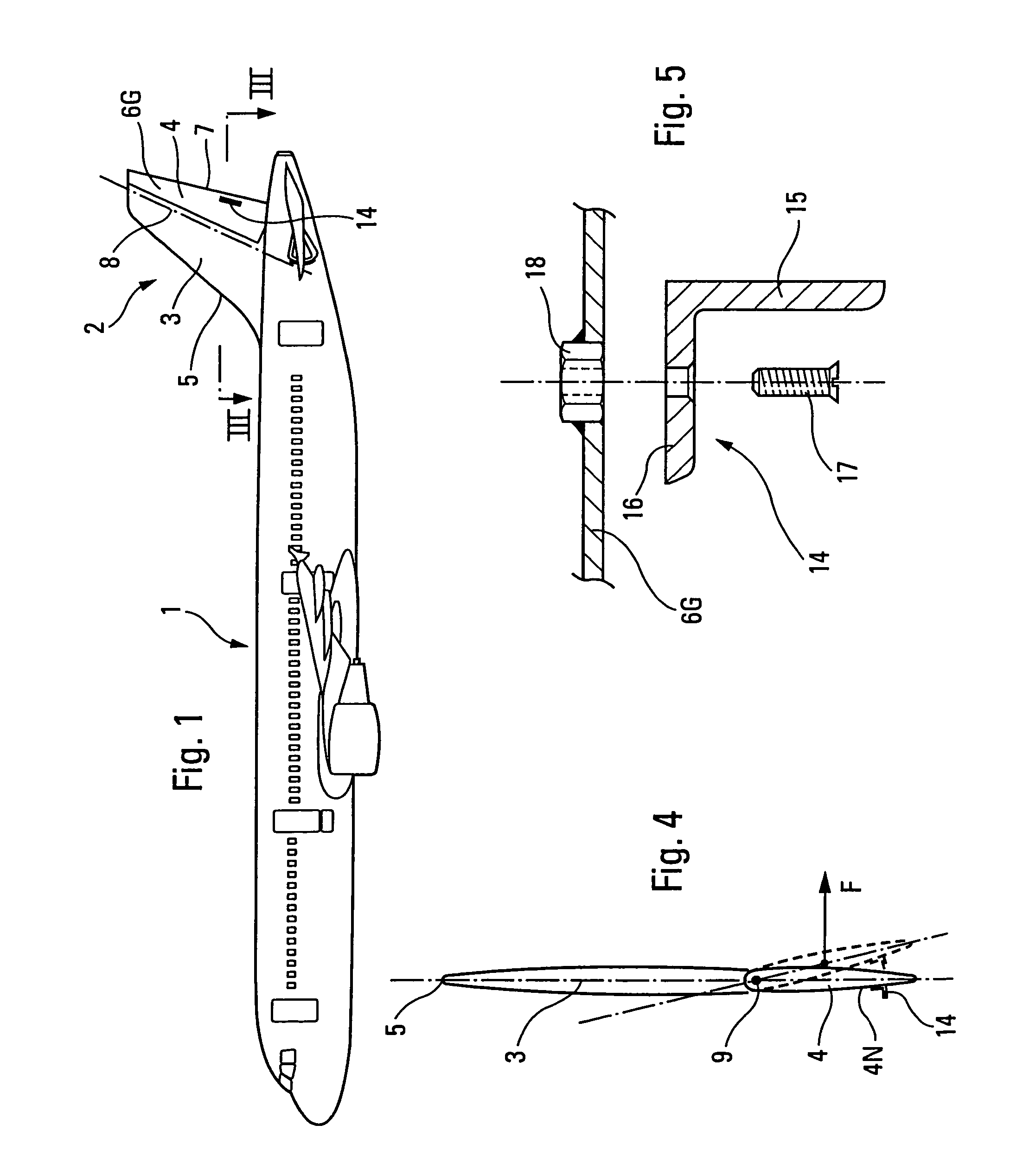
[0033]The large-capacity civil aircraft 1, shown in FIG. 1, comprises, in the vicinity of its tail, a rudder assembly 2 comprising a fixed vertical stabilizer 3 and a mobile rudder 4.
[0034]At the forward end, the fixed vertical stabilizer 3 has a leading edge 5, constituting the leading edge of the said rudder assembly 2.
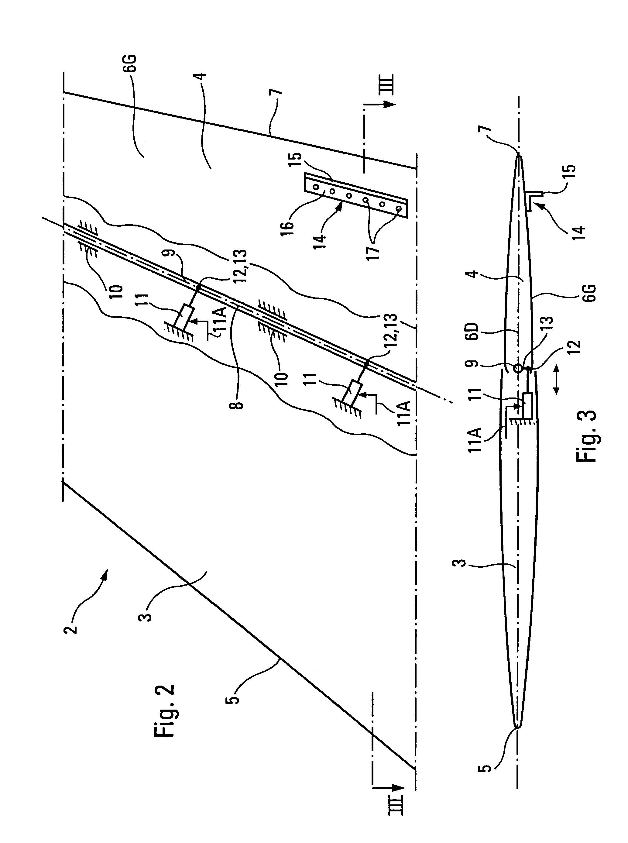
[0035]Moreover, the said mobile rudder 4 comprises two lateral aerodynamic surfaces 6G and 6D meeting at the rear end of the aircraft 1 in order to form the trailing edge 7 of the said rudder 4 and of the said rudder assembly 2.
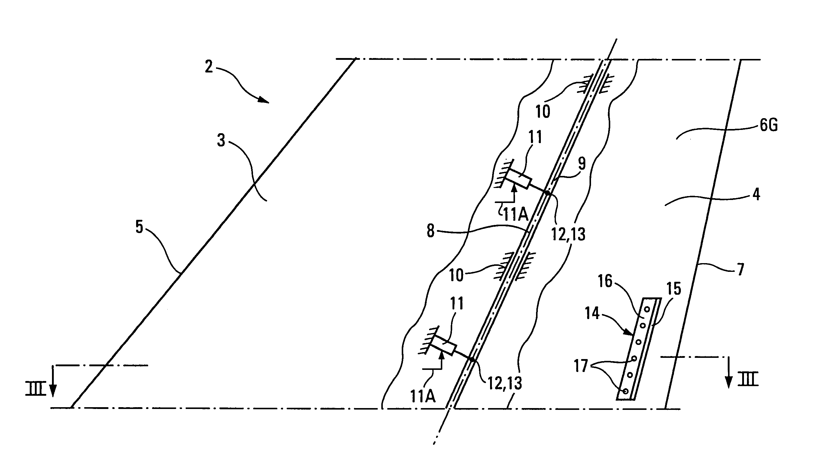
[0036]The rudder 4 is mounted such that it rotates with respect to the fixed vertical stabilizer 3, about an articulation axis 8, defined by a shaft 9 integral with the rudder 4 and able to swivel in bearings 10, integral with the vertical stabilizer 3.
[0037]The shaft 9, and therefore the rudder 4, can be driven in rotation, in both directions, about the articulation axis 8 by jacks 11 mounted in the vertical stabilizer 3 and controlled by th...
PUM
 Abstract
Description
Claims
Application Information