Tool holder for a rotary hammer

a tool holder and rotary hammer technology, which is applied in the field of tool holder for rotary hammer, can solve the problems of inconvenient use, inconvenient maintenance, and inability to meet the needs of non-standard tools or bits, so as to maintain the structural strength of the holder body and reduce the circumference of additional holes

Inactive Publication Date: 2008-03-04
BLACK & DECKER INC
View PDF30 Cites 19 Cited by
  • Summary
  • Abstract
  • Description
  • Claims
  • Application Information

AI Technical Summary

Benefits of technology

[0008]The object of the invention is to produce a tool holder with driving ribs which are wear resistant, robust and enable a simple construction of the tool holder.
[0013]The additional through holes for receiving the inserts are formed by simply drilling two or more axially offset circular cross sectioned through holes through the wall of the tool holder main body (holder body). The same drilling tool can be used for drilling each circular cross sectioned hole, with the tool or the holder body being moved axially between drilling operations. For longer driving ribs a greater number of circular cross-sectioned holes can be drilled in order to minimise the circumference of the additional holes in order to maintain the structural strength of the holder body. The circular cross-sectioned holes may each have the same diameter.

Problems solved by technology

When the hammer to which the tool holder is fitted is used in a hammering mode, the tool or bit reciprocates and so the axial driving groove, which engages the axial driving rib reciprocates with respect to the driving spline causing a considerable amount of wear, especially in a rotary hammer mode in which torque is transmitted from the driving rib to the driving groove.
The wear means that the tool holder may have to be replaced by a new tool holder after prolonged use of the tool holder.
A problem with this is that a non-standard tool or bit is required with driving grooves specially shaped to engage the rolling bodies.
While EP335,795 provides hard wearing driving ribs, the recess in the tool holder main body is of complex shape and relatively difficult to machine.
Again, DE199 58 342 provides hardened driving ribs, however, the axially extending recesses undermine the structural strength of the forward end of the tool holder main body.
Also, the driving insert is subject to axial vibration due to the relative reciprocation between the driving groove and the rib, which can weaken the fixing between the insert and the tool holder body.
The driving insert is a relatively large part, and as it is made of carbide material then it is relatively expensive.

Method used


Image

  • Tool holder for a rotary hammer
  • Tool holder for a rotary hammer
  • Tool holder for a rotary hammer

Examples


Embodiment Construction

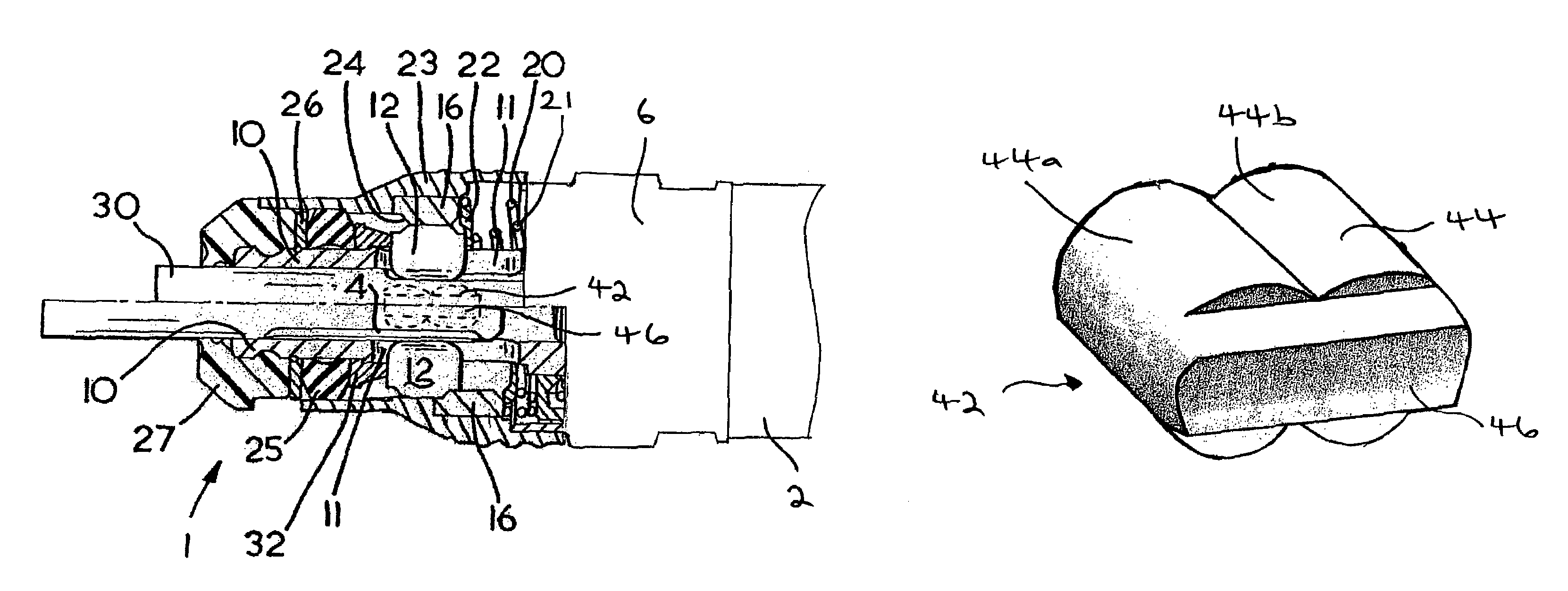
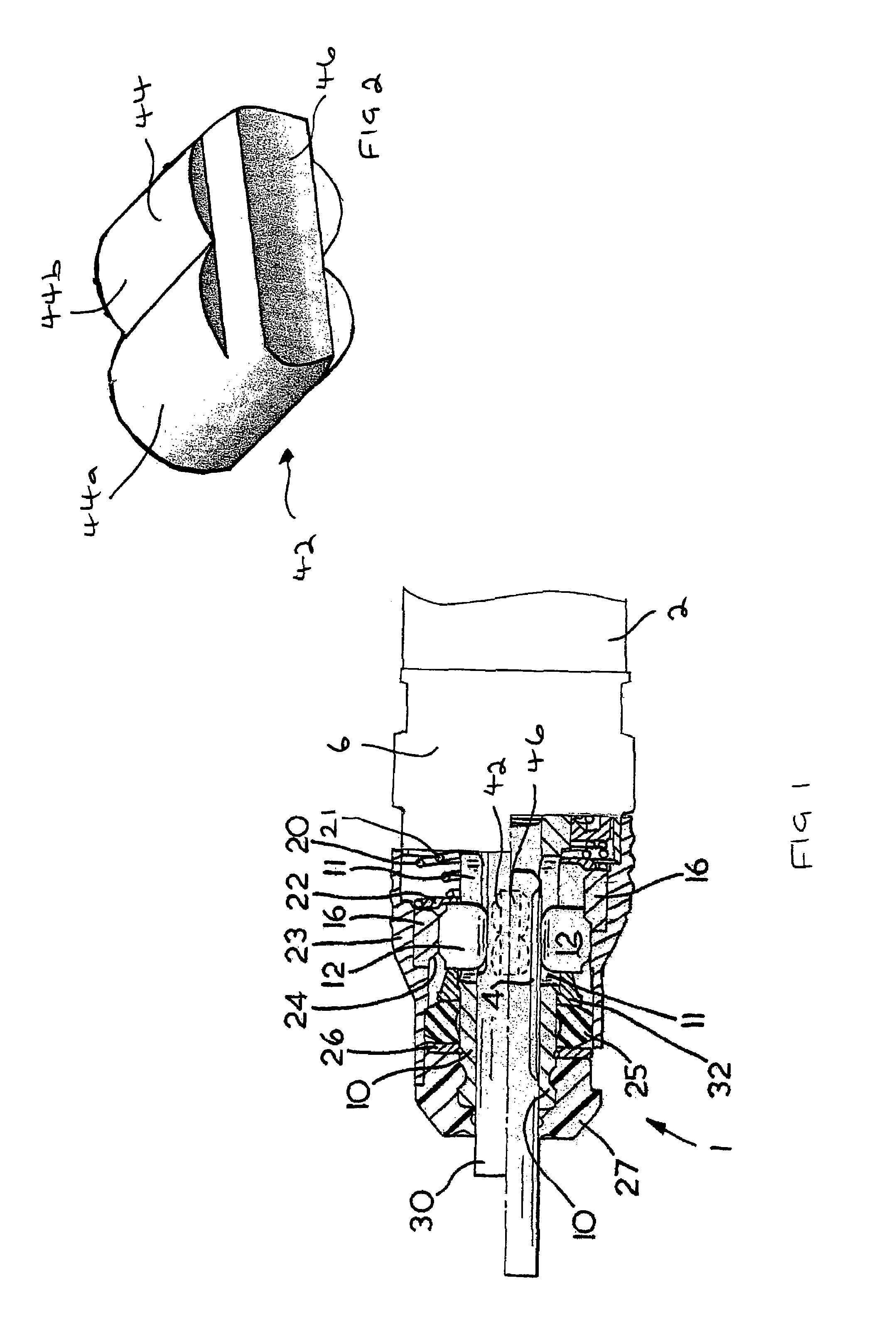
[0035]The tool holder 1 shown in FIG. 1 has a tube-like tool holder main body 10, which has a continuous coaxial receiving opening. The holder body 10 sits with its rear end in a housing part 2, consisting of metal, of a rotary hammer, not otherwise shown. A tool or bit fitted within the tool holder will receive repeated impacts on its rearward end by the hammering mechanism of the hammer, as is well known in the art, when the rotary hammer is operated in a hammer only or a rotary hammer mode. In addition rotary drive will be transmitted to the tool holder by the rotary drive train of the hammer, as is well known in the art, and thereby to a tool or bit mounted within the tool holder, when the hammer is operated in a drilling only or a rotary hammer mode.

[0036]On the front end of the housing part 2 there is seated an alignment sleeve 6, which, in a manner not shown specifically, is in interlocking engagement with the housing part 2 and is in interlocking engagement with the holder b...


PUM

PropertyMeasurementUnit
constant diameteraaaaaaaaaa
adhesionaaaaaaaaaa
diameteraaaaaaaaaa

Abstract

A tool holder (1) for a rotary hammer which has a tube like tool holder main body (10) having a side wall formed with through holes (11) for receiving corresponding locking bodies (12) and formed with additional through holes (40). The tool holder includes hardened metal driving ribs (46) each located on an insert (42) and the inserts are fitted within the additional through holes (40) so that the ribs extends axially and radially inwardly of the radially inward facing surface of the holder body. The locking bodies (12) are arranged to releaseably engage a corresponding axial closed groove of a tool or bit inserted within the tool holder and the ribs (46) are arranged to releaseably engaging a corresponding axial rearwardly open driving grooves of a tool or bit inserted within the tool holder. To simplify the process for forming the tool holder body (10) each additional through hole (40) is formed by at least two overlapping axially offset circular cross-sectioned through holes (40a, 40b) and the corresponding insert has a base (44) shaped to fit the through hole (40).

Description

[0001]The present invention relates to a tool holder for a rotary hammer.BACKGROUND OF THE INVENTION[0002]Such tool holders generally have a main tube like body with an open forward end within which a chisel tool or drill bit may be inserted. The tool or bit is generally formed with at least one axially extending closed groove towards the rearward end of the tool shank. The tube like body of the tool holder is generally formed with at least one through hole, within the or each of which is located a locking body. The locking body is arranged so that it can be radially displaced between a radially inward locked position and a radially outward unlocked position. The locking body is generally held in the locked position by a locking ring of the tool holder, and in the locked position the locking body engages within the closed groove of the tool or bit. The closed groove is generally axially longer than the locking body and so the tool or bit is locked in the tool holder main body so as ...

Claims


Application Information

Patent Timeline
Patent Type & Authority Patents(United States)
IPC IPC(8): B23B31/107B25D17/08B28D1/14
CPCB25D17/088B25D2217/0038Y10T279/17811Y10T279/17743Y10T279/17042Y10T279/17085
Inventor BUCHHOLZ, ACHIM
Owner BLACK & DECKER INC
Why Eureka
Try Eureka