
Electric connector having power cable retaining structure

Inactive Publication Date: 2008-03-04
CHEN JUI LUNG
View PDF5 Cites 14 Cited by
  • Summary
  • Abstract
  • Description
  • Claims
  • Application Information

AI Technical Summary

Benefits of technology

[0007]It is another object of the present invention to provide an electric connector assembly, which has a stop flange extending around the periphery to prohibit outside water from entering the inside of the electric connector assembly, preventing a short-circuit.

Problems solved by technology

This design of using a stop member to fix the position of the power cable is still not satisfactory in function.
For example, when a different diameter of power cable is used, a different size of stop member shall be installed, i.e., one stop member cannot fit cables of different diameters.
Further, if an electric plug or socket does not provide an effective water resistant means, water may enter the inside of the connector body to wet the internal circuit and to further cause the electric apparatus to break down or to leak out electricity, and the user may be shocked when touching the wet electric plug or socket.

Method used


Image

  • Electric connector having power cable retaining structure
  • Electric connector having power cable retaining structure
  • Electric connector having power cable retaining structure

Examples


Embodiment Construction

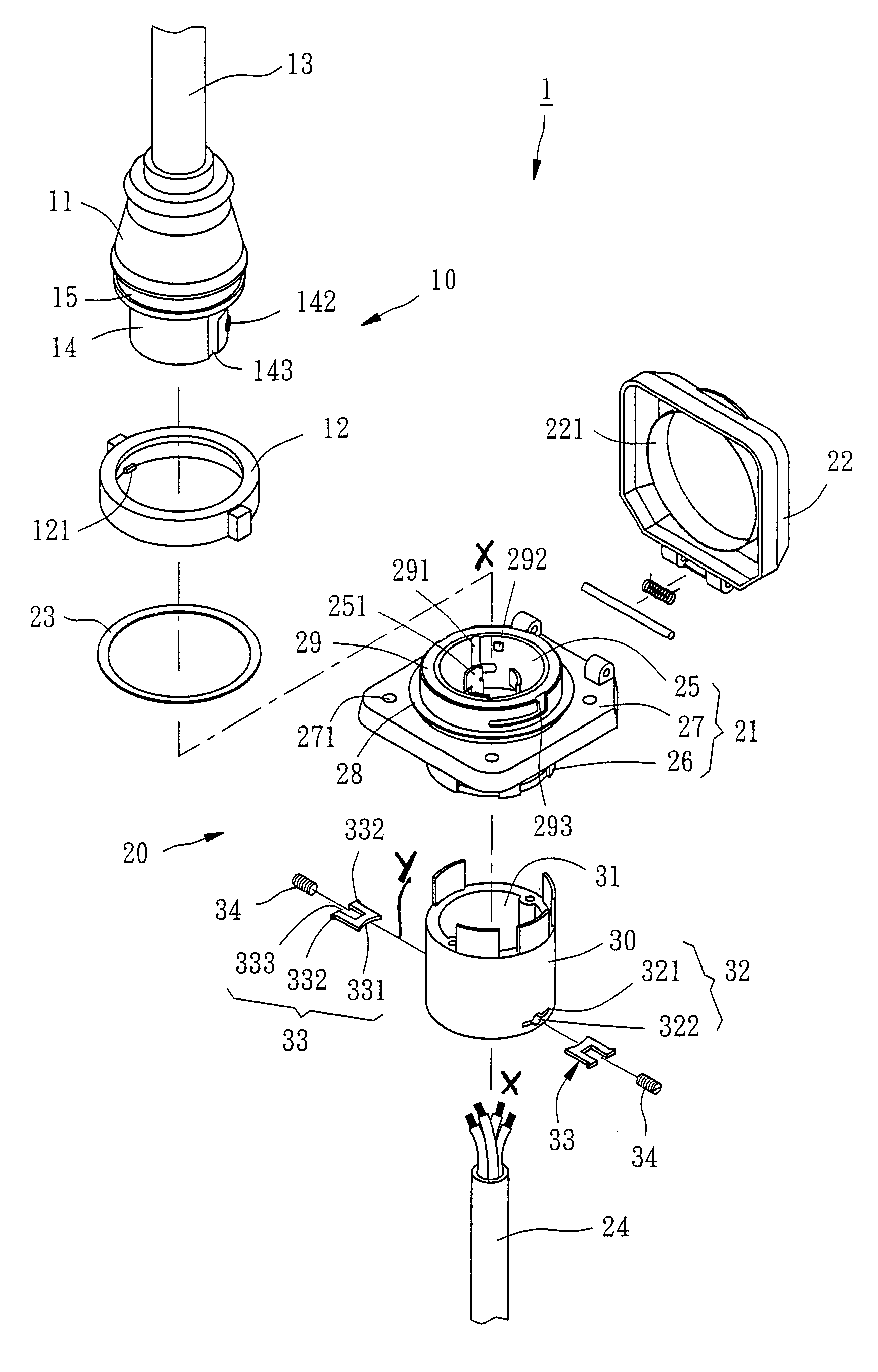
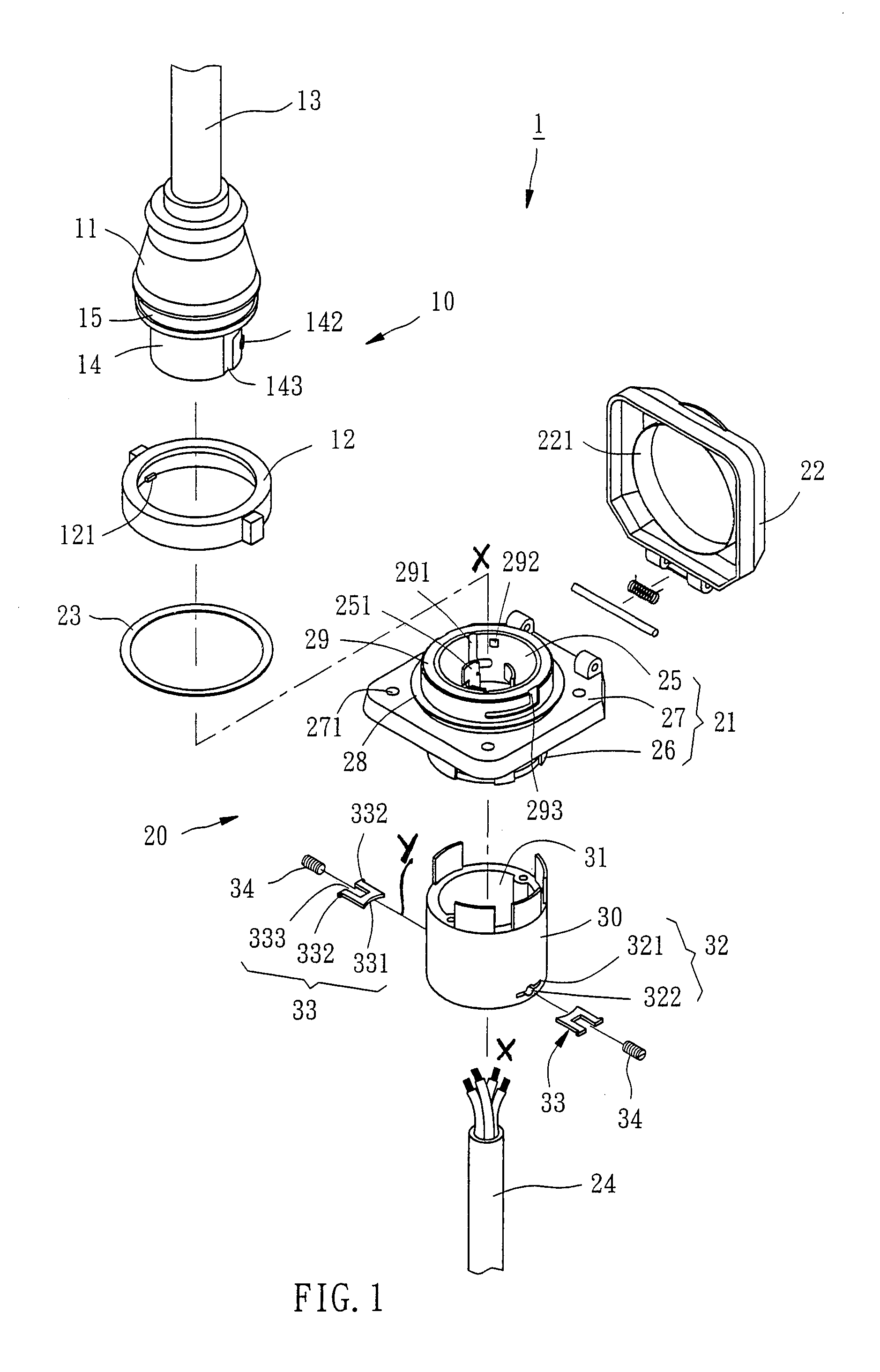
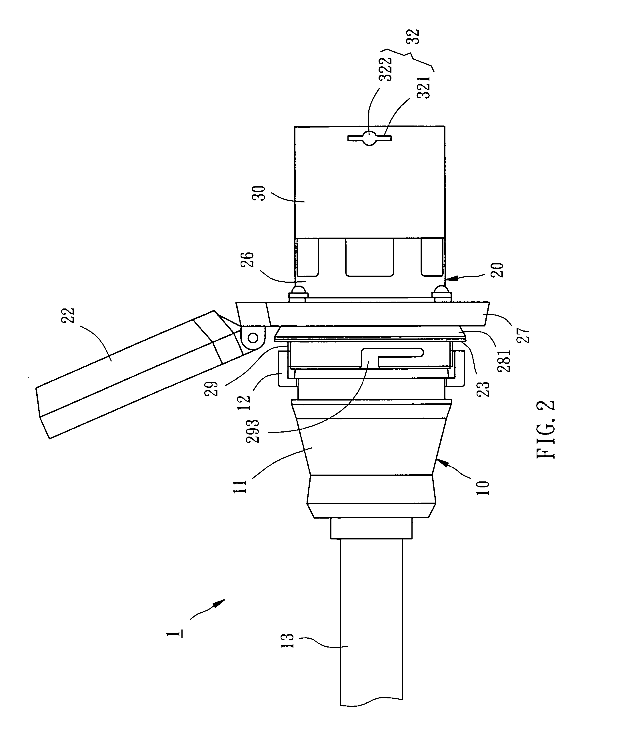
[0019]As shown in FIGS. 1-9, an electric connector assembly 1 in accordance with a preferred embodiment of the present invention comprises a pair of coupled electric connectors, namely a female electric connector, i.e. an electric socket 10, and a male electric connector, i.e. an electric plug 20. In this embodiment, the power cable retaining structure is shown applied to the electric plug only for easy illustration purpose.

[0020]Referring to FIGS. 1-4, the electric socket 10 comprises a socket body 11, a coupling member 12, and a power cable 13. The socket body 11 has a coupling portion 14 axially forwardly extended from the front side thereof, and a locating groove 15 extending around the periphery. The coupling portion 14 has three terminal slots 141 each holding a respective conductive terminal (not shown), and two raised portions 142 and two L-shaped grooves 143 and a guide rib 144 respectively formed on the periphery thereof. The coupling member 12 is coupled to the locating g...


PUM


Abstract

An electric connector includes a connector body having contact terminals mounted in a first end thereof and an axial through hole axially formed in a second end thereof opposite to the first end. A power cable is inserted into the axial through hole of the connector body and electrically connected to the contact terminals. Two retaining members are transversely mounted in the connector body and engaged at two opposite sides of the power cable to hold the power cable in the axial through hole of the connector body. The retaining members are movable relative to each other to adjust a pitch therebetween subject to a diameter of the power cable.

Description

BACKGROUND OF THE INVENTION[0001]1. Field of the Invention[0002]The present invention relates generally to electric connectors, such as electric sockets or electric plugs, and more particularly to an electric connector having a power cable retaining structure.[0003]2. Description of the Related Art[0004]Conventional electric connectors, either electric plugs or electric sockets, commonly comprise a connector body and a power cable. The connector body holds positive and negative terminals that are respectively soldered to the positive and negative poles of the power cable by means of a respective metal conductive plate. Further, a stop member is capped on the power cable to fix the power cable in position, preventing disconnection of the power cable from the metal conductive plates to break the circuit when the power cable is stretched. This design of using a stop member to fix the position of the power cable is still not satisfactory in function. For example, when a different diamet...

Claims


Application Information

Patent Timeline
IPC IPC(8): H01R13/62
CPCH01R13/5812H01R13/5837H01R13/5213H01R13/595H01R13/625
Inventor CHEN, TSANG-I
Owner CHEN JUI LUNG
Features
  • Generate Ideas
  • Intellectual Property
  • Life Sciences
  • Materials
  • Tech Scout
  • Unparalleled Data Quality
  • Higher Quality Content
  • 60% Fewer Hallucinations
Learn More