Drainage catheter having an expandable retention member

a technology of expanding retention member and drainage catheter, which is applied in the field of drainage catheter, can solve the problems of patient discomfort due to the construction, the size of the catheter is difficult to insert, and the patient is uncomfortabl

Inactive Publication Date: 2008-03-04
APPL MEDICAL RESOURCES CORP
View PDF23 Cites 6 Cited by
  • Summary
  • Abstract
  • Description
  • Claims
  • Application Information

AI Technical Summary

Benefits of technology

[0007]A drainage catheter having an elongate tube and a retention member disposed at the distal end of the elongate tube. The retention member is adapted for movement between a low-profile state facilitating insertion of the catheter and a high-profile state facilitating retention of the catheter in a body cavity. The retention member is oval or bulb shaped in the high-profile state and is cylindrical in the low-profile state. This construction of the catheter provides for less traumatic insertion and withdrawal of the catheter. A pusher or stylet is provided to facilitate insertion of the catheter. The retention member is preferably formed of a woven mesh that facilitates drainage of fluid into the elongate tube.

Problems solved by technology

There are several disadvantages associated with the Foley catheter, the most significant of which is patient discomfort due to the construction of the catheter.
This size of catheter is difficult to insert and is very uncomfortable for the patient.
Patient frustration sometimes leads to inadvisable patient removal of the catheter, even with the balloon inflated.
This of course can be very damaging and traumatic to the patient.
The hard rubber tip of the Foley catheter also contributes to patient discomfort.
In particular, as the bladder empties, it collapses and the hard rubber tip begins to rub against the wall of the bladder causing irritation.

Method used


Image

  • Drainage catheter having an expandable retention member
  • Drainage catheter having an expandable retention member
  • Drainage catheter having an expandable retention member

Examples


Embodiment Construction

[0016]Co-pending U.S. patent application Ser. No. 09 / 598,014 filed Jun. 20, 2000, entitled Drainage Catheter, is incorporated herein by reference.

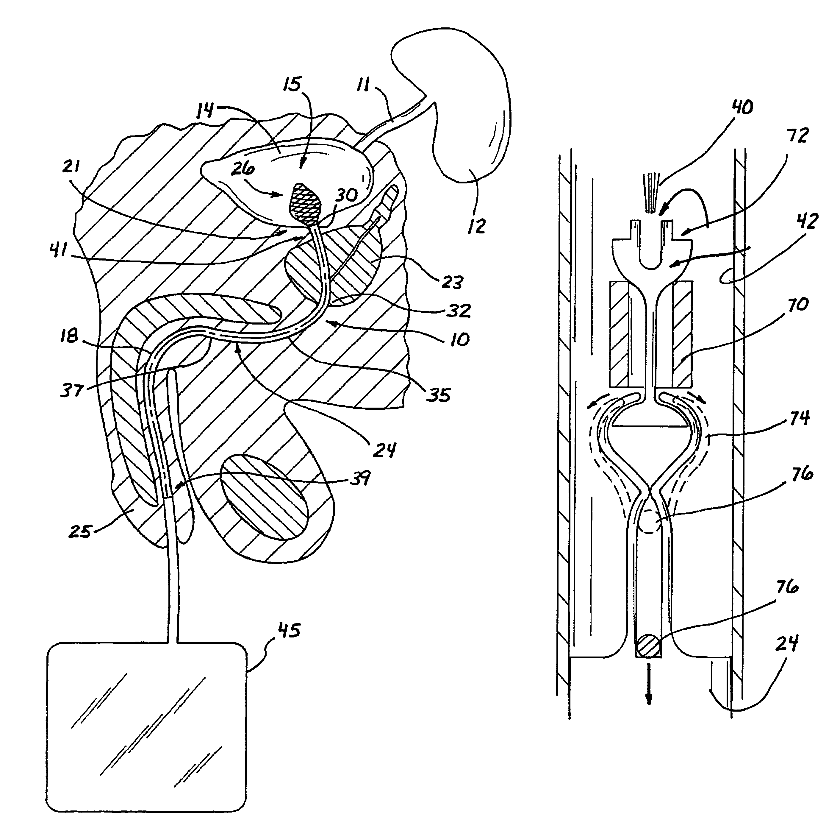
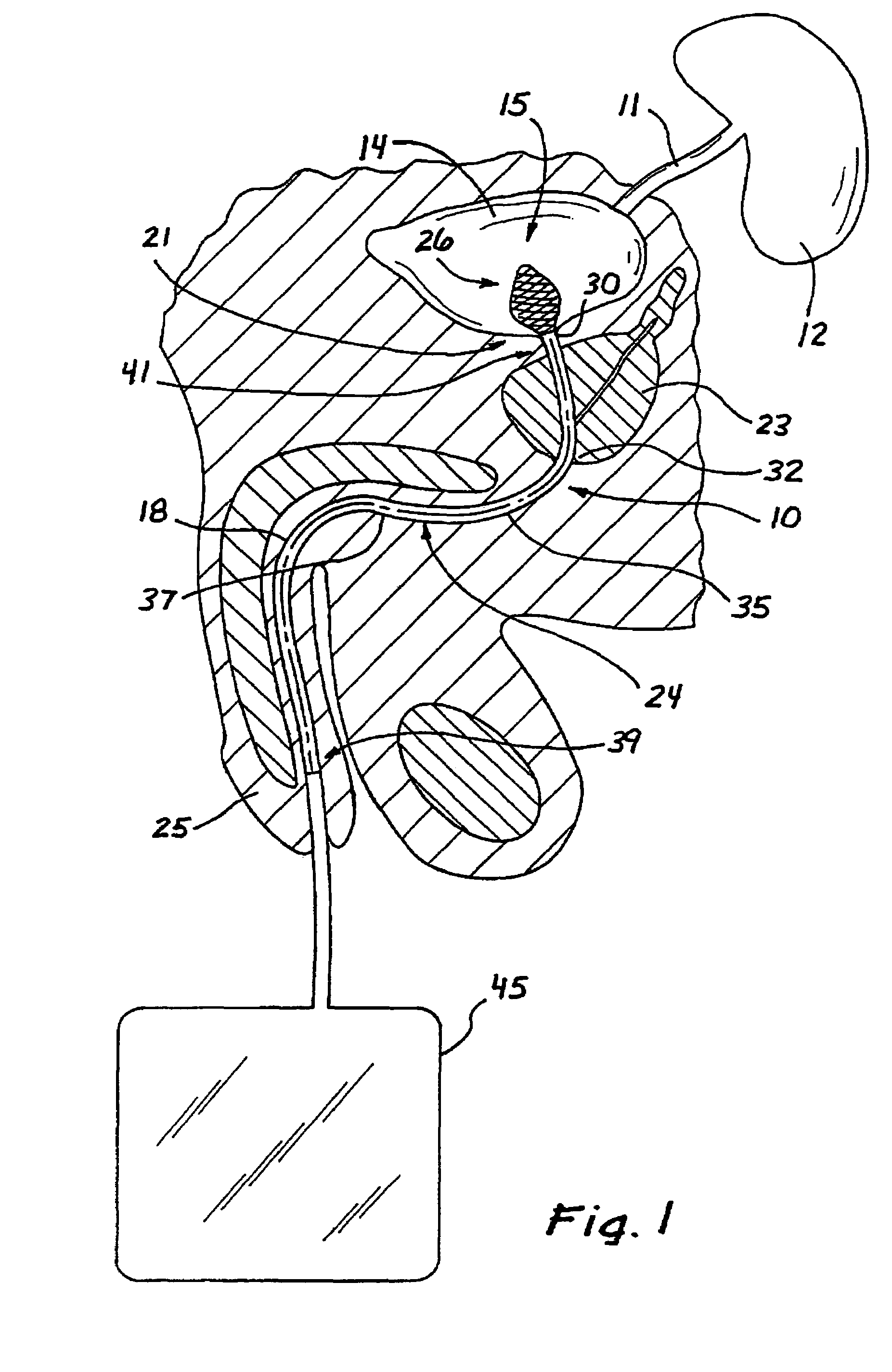
[0017]Referring to FIG. 1, a drainage catheter 10 adapted for use in the urinary tract of a patient is illustrated. The urinary tract includes a ureter 11 extending in fluid communication between a kidney 12 and a bladder 14 having a bladder cavity 15. A urethra 18 begins at a bladder neck 21 and passes outwardly through a prostate 23 and a meatus 25 of a penis 27. When urethra 18 is compromised or obstructed, urine cannot naturally drain from bladder 14 and it becomes desirable to open urethra 18 or otherwise provide a fluid passage from bladder 14 through urethra 18 and meatus 25.

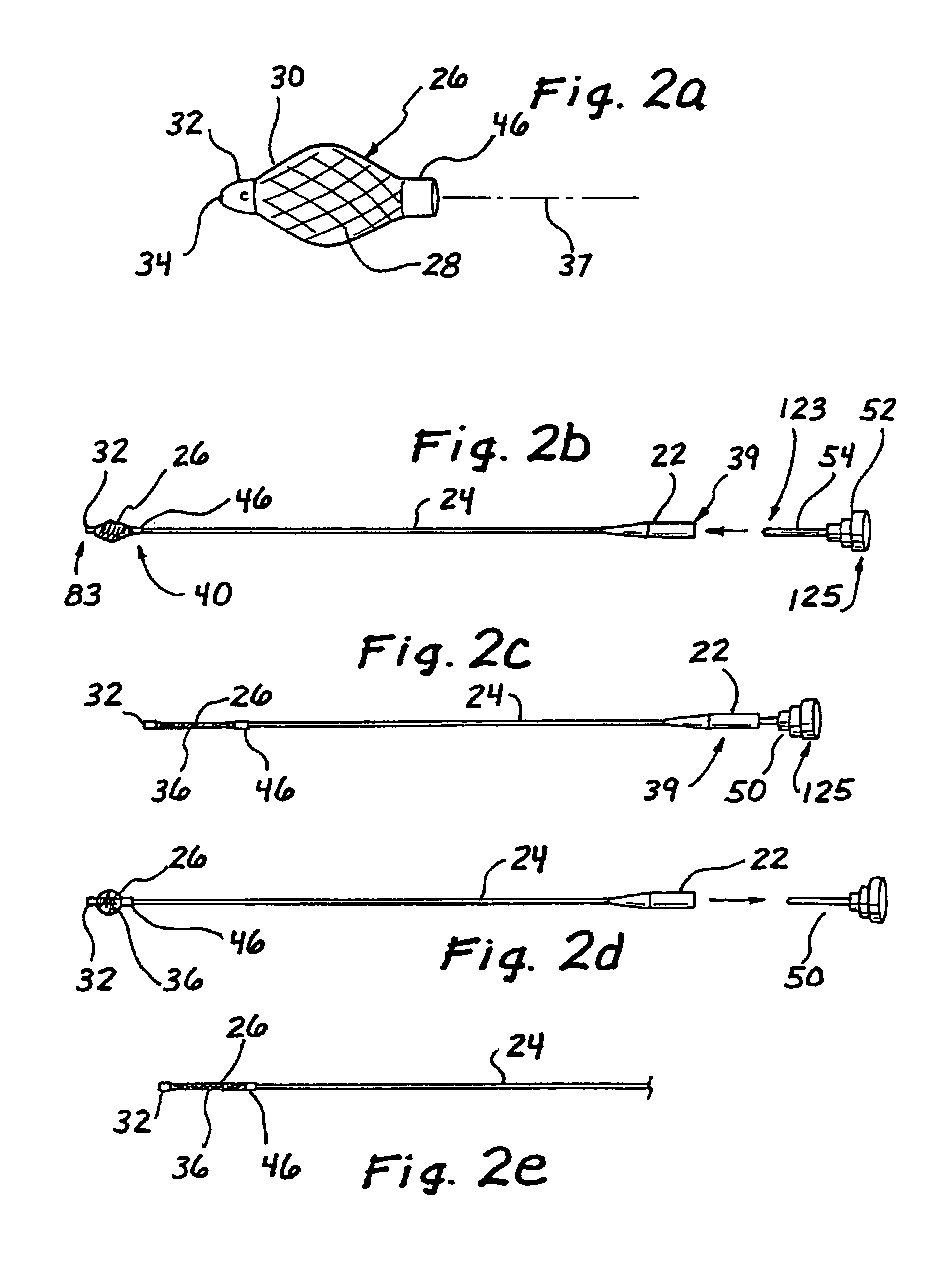
[0018]Catheter 10 includes an elongate tube 24 having a wall 35 extending distally to a retention member 26. Tube 24 extends along an axis 37 between a proximal end 39 and a distal end 41. Retention member 26 can be formed of a mesh. With catheter 10 operatively...


PUM


Abstract

A drainage catheter is adapted to drain fluid from the body cavity through a body conduit and includes an elongate tube and a retention member disposed at the distal end of the elongate tube. The retention member is adapted for movement between a low-profile state facilitating insertion of the catheter and a high-profile state facilitating retention of the catheter in its operative position. A woven mesh forms at least a portion of one of the tube and the retention member. The woven mesh can be formed of filaments heat-settable so that the catheter automatically moves to the high-profile state. Insertion of the catheter can be facilitated using a stylet which can be removed after insertion to permit the catheter to automatically return to its high-profile state.

Description

BACKGROUND OF THE INVENTION[0001]1. Field of the Invention[0002]This invention generally relates to medical devices and, more specifically, to drainage catheters adapted for use in draining a fluid from a body cavity.[0003]2. Discussion of the Prior Art[0004]Urinary drainage catheters are used to provide an outlet for the urinary bladder when the urethra is compromised or obstructed, such as when the patient is incapable of controlling the urinary system due to sedation or lack of mental capacity. A typical urinary catheter is the Foley catheter, which is a thick-walled rubber tube with an inflatable balloon near its distal end. The Foley catheter is inserted through the urethra and into the bladder cavity. When disposed, the balloon is inflated within the bladder cavity to a size that prevents the distal end from passing back through the bladder neck.[0005]There are several disadvantages associated with the Foley catheter, the most significant of which is patient discomfort due to ...

Claims


Application Information

Patent Timeline
Patent Type & Authority Patents(United States)
IPC IPC(8): A61M31/00A61M37/00A61MA61M29/00
CPCA61M25/0017A61M25/04A61M29/02A61M2025/0063A61M2210/1085A61M2210/1096
Inventor HART, CHARLES C.PINEDJIAN, RAFFI S.PRAVONG, BOUN
Owner APPL MEDICAL RESOURCES CORP
Why Eureka
Try Eureka