Dilator

a technology of dilators and guidewires, which is applied in the direction of multi-lumen catheters, catheters, and guide wires, etc., can solve the problems of high cost of introducers, inability to smoothly insert introducers, and complicated tasks, and achieve the effect of reducing the opening in the vessel

Inactive Publication Date: 2016-11-17
YUGEN KAISHA OKID
View PDF23 Cites 0 Cited by
  • Summary
  • Abstract
  • Description
  • Claims
  • Application Information

AI Technical Summary

Benefits of technology

[0025]According to the invention described in claim 6, because the recessed portion is formed by recessing a part of the surface of the dilator excluding the distal end face and the rear end face, and the one end of the second through-hole is open in the recessed portion, it is less likely to damage the inner wall of the vessel by corner portions of the opening.
[0026]According to the invention described in claim 7, because the recessed portion is formed as a long groove extending in a direction along the axis of the dilator and because a plurality of rec

Problems solved by technology

However, with the conventional method of inserting two guidewires into the vessel through one insertion puncture formed in the skin, a step between an outer peripheral portion of the dilator projecting from the sheath tip and an outer peripheral portion of the sheath tip made resistance when inserting the introducer while dilating the insertion puncture, and thus the introducer could not be

Method used


Image

  • Dilator
  • Dilator
  • Dilator

Examples


first embodiment

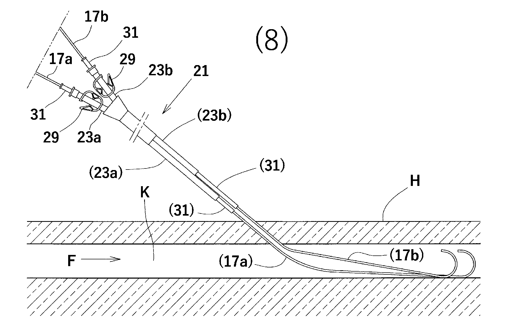
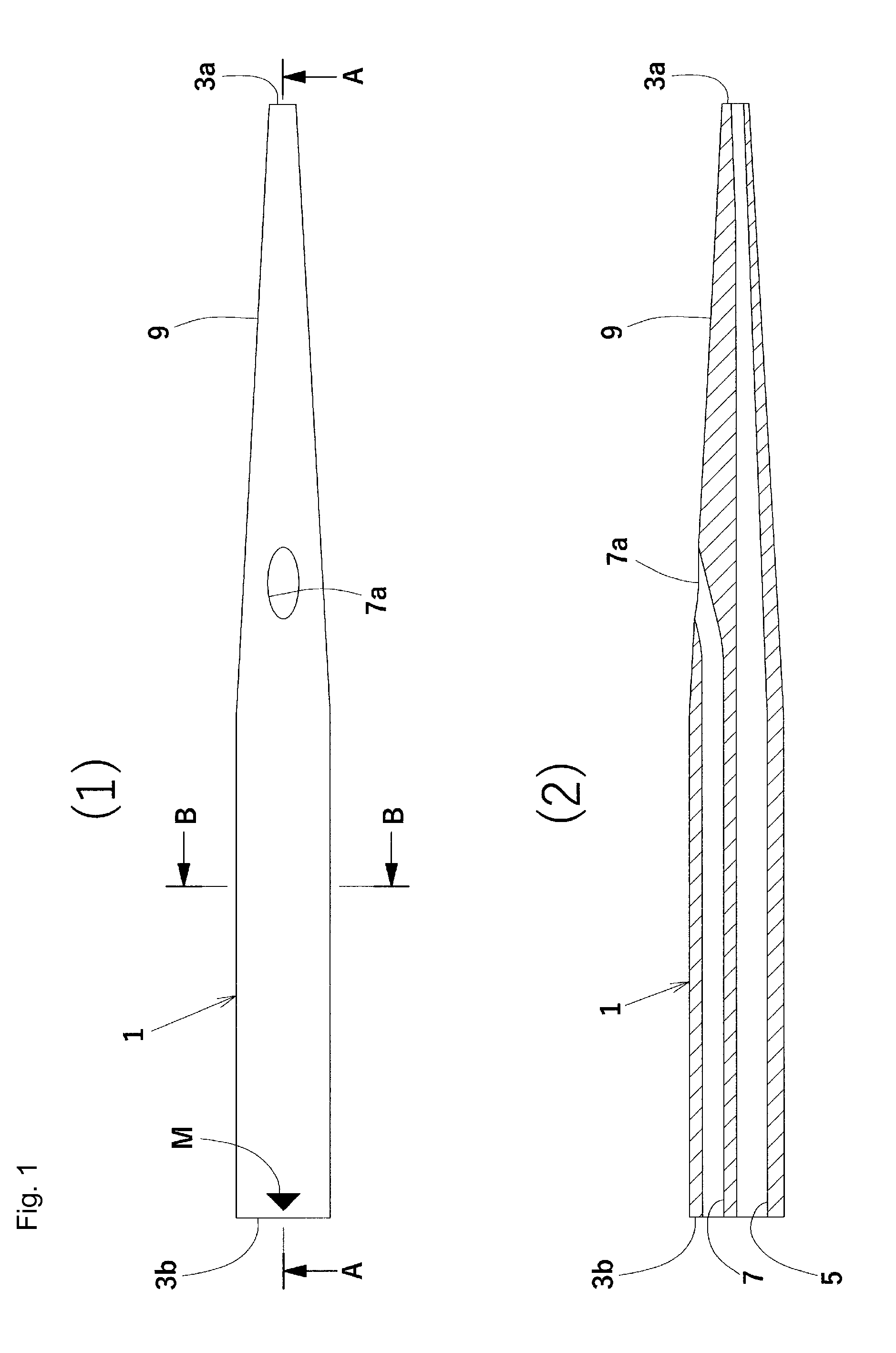
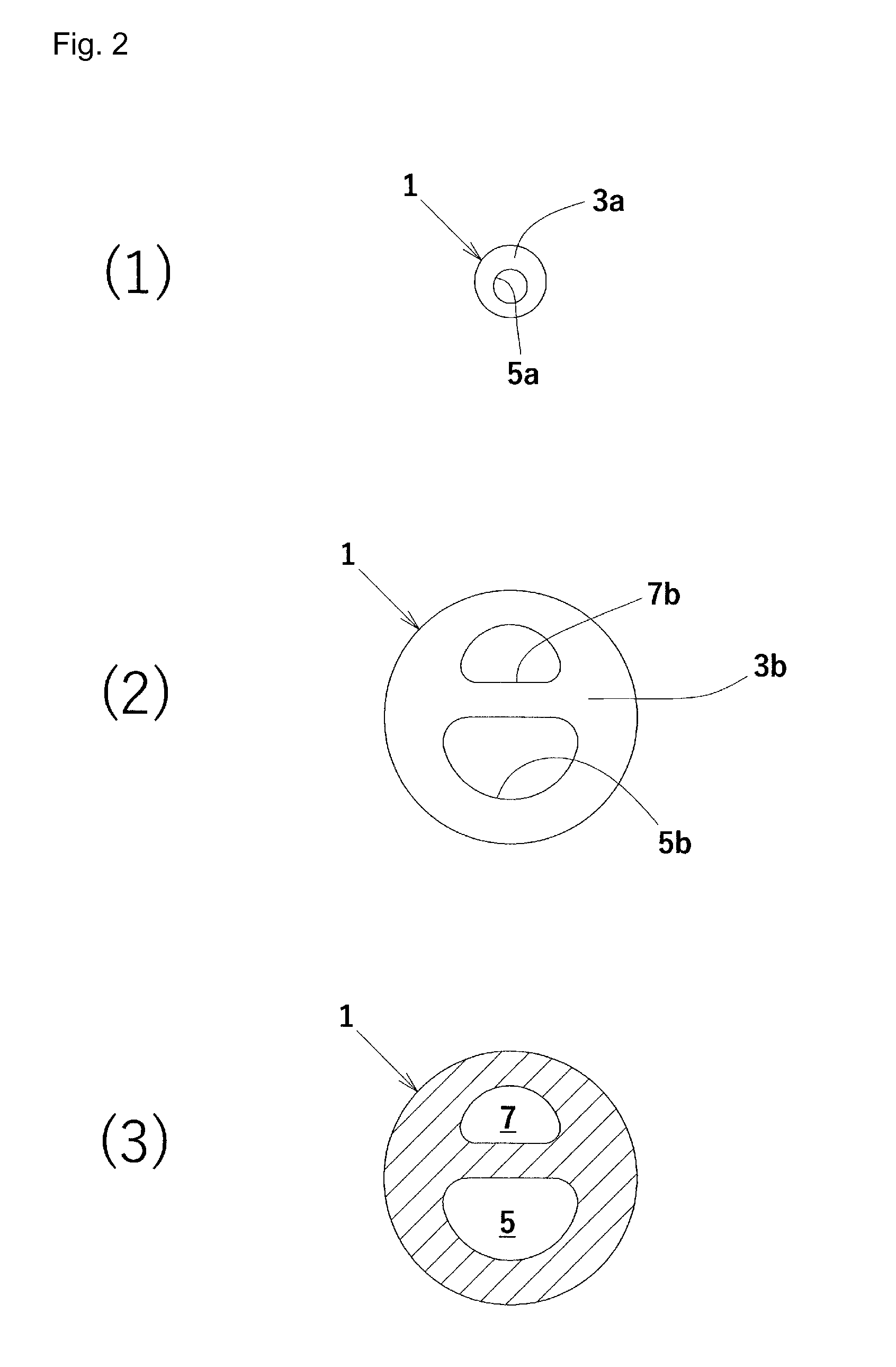
[0038]A first embodiment according to the present invention will be described in detail with reference to accompanying drawings FIG. 1 through FIG. 8. Reference numeral 1 in (1) and (2) of FIG. 1 denotes an example of a dilator according to the present invention. The dilator 1 shown in these figures is used to dilate an opening formed in the skin by a puncture needle to facilitate the insertion of a catheter or used when inserting guidewires into a vessel, and is made from a stem-like member having a generally circular transverse section. The dilator 1 is made from resin having elasticity to some extent, for example, polypropylene resin, polyethylene resin, and nylon resin. The dilator 1 is provided with a first through-hole 5 pierced over an entire region of the dilator 1 from a distal end face 3a to a rear end face 3b in a longitudinal direction of the dilator 1, a second through-hole 7, which is a different through-hole from the first through-hole 5, pierced over a region of the ...

second embodiment

[0074]In the above-mentioned first embodiment, an example was shown in which the opening 7a of the second through-hole 7 is provided in the surface of the tapered portion 9 of the dilator 1. However, as in the second embodiment shown in FIG. 9, only one recessed portion 33 may be formed in a part of the surface of the tapered portion 9 by recessing one location thereof and the opening 7a may be formed in the recessed portion 33. The recessed portion 33 is formed to extend long in a direction along the axis of the dilator 1.

[0075]According to the dilator 1 of the second embodiment, because the recessed portion 33 is formed by recessing a part of the surface of the dilator 1 excluding the distal end face 3a and the rear end face 3b, and the one end of the second through-hole 7 is open in this recessed portion 33, it is less likely to damage the inner wall of the vessel K by corner portions of the opening 7a.

[0076]Note that, in this second embodiment, the opening 7a of the second thro...

third embodiment

[0077]In the example shown for the above-mentioned second embodiment, only one recessed portion 33 was formed and the opening 7a of the second through-hole 7 was formed in this recessed portion 33. However, three recessed portions 33, as in the third embodiment shown in FIG. 10 and FIG. 11 may be provided, and the opening 7a of the second through-hole 7 may be formed in one of the three recessed portions 33. Each recessed portion 33 is formed as a long groove extending in a direction along the axis of the dilator 1, and the recessed portions 33 are formed in the surface of the tapered portion 9 at equivalent angles and at a certain distance apart from each other in the circumferential direction. In the third embodiment, while each of the recessed portions 33 was formed in some region in a direction along the axis of the dilator 1, the invention is not limited thereto, and the recessed portions 33 may also be provided along the entire region from the distal end face 3a to the rear en...


PUM


Abstract

The invention provides a dilator having characteristics as an inexpensive instrument that allows insertion of a guidewire for assisting insertion of a catheter into a vessel in a simple and smooth manner. A first through-hole 5 into which a guidewire can be inserted is pierced over an entire region of a dilator 1 from a distal end face 3a to a rear end face 3b in the longitudinal direction of the dilator. A second through-hole 7 into which a guidewire can be inserted is pierced over a region of the dilator 1 from a midway to the rear end face 3b in the longitudinal direction of the dilator. A tapered portion 9 is formed such that it is tapered toward the distal end face 3a. An opening 7a a of the second through-hole 7 is open on the surface of the tapered portion 9.

Description

BACKGROUND OF THE INVENTION[0001]1. Field of the Invention[0002]The present invention relates to a dilator for assisting subcutaneous insertion of a catheter with two fluid passages into a vessel via an insertion puncture.[0003]2. Description of the Related Art[0004]U.S. 2014 / 0088510 A describes subcutaneous insertion of a catheter system 10 with two internal lumens, or fluid passages, into a vessel 4, wherein two guidewires 26A and 26B are inserted into the vessel 4 prior to the insertion of the catheter system 10 such that two distal tip portions 18A and 18B of the catheter system 10 are respectively inserted into the vessel 4 via the guidewires 26A and 26B.[0005]However, a method for inserting the first guidewire 26A and the second guidewire 26B into the vessel 4 is not detailed in U.S. 2014 / 0088510 A. As described in [Related Art] of JP 2002-291902 A, the insertion method includes, for example, a method using an outer tube having a puncture needle inserted therein and an introdu...

Claims


Application Information

Patent Timeline
IPC IPC(8): A61M25/06A61M25/09
CPCA61M25/09A61M25/0662A61M25/0026A61M25/007A61M25/09041A61M29/00
Inventor OKADA, YOSUKE
Owner YUGEN KAISHA OKID
Why Eureka
Try Eureka