Self-aligning telescope

a telescope and self-aligning technology, applied in the field of telescope control systems, can solve the problems of affecting the complexity of the orientation and alignment of the telescope for less experienced users, and the potential inaccurateness of the shape-oriented alignment system, so as to increase the accuracy of the telescope's self-alignment and quick and accurate orientation

Active Publication Date: 2008-03-04
MEADE INSTRUMENTS
View PDF28 Cites 16 Cited by
  • Summary
  • Abstract
  • Description
  • Claims
  • Application Information

AI Technical Summary

Benefits of technology

[0008]Embodiments of the present disclosure include advantageous self-aligning telescope control systems that quickly and accurately orient a telescope. For example, in an embodiment, a telescope control system acquires at least one image of stars in an alignment area, attributes intensity values to some of the stars, determines relationships based on the intensity values, and matches the relationships with known relationships about celestial bodies to quickly orient the telescope with known celestial mappings of the sky. Once oriented, the telescope control system can then slew to a desired celestial object based on, for example, user or system selected objects. In an embodiment, the telescope control system may slew to additional alignment areas, and quickly reorient the telescope to increase the accuracy of the telescope's self alignment.
[0009]Certain embodiments provide self-aligning telescope control systems with additional information such as, for example, time, date, location with respect to the earth, celestial coordinates of an alignment star or alignment area, relative brightness of a group of stars in an alignment area, distances between the stars in the group of stars in the alignment area, patterns formed by stars in vicinity of the alignment star, combinations of the foregoing, or the like. In certain embodiments, determining a telescope's location with respect to earth may include use of a virtual location, thereby substantially avoiding often confusing initial precision leveling techniques. For example, a telescope control system may orient with respect to the horizon and / or a predetermined compass direction in response to receiving information from a level sensor, an electronic compass, or the like. Such self orientation creates a virtual location for the telescope, where the virtual location at least roughly corresponds to a location where the telescope's position with respect to the horizon would be considered accurately leveled.
[0010]In still other embodiments, the control system may advantageously perform additional or alternative alignments, such as, for example, measuring a sidereal drift of an alignment star to improve the accuracy of the mapping.
[0011]Once aligned, other embodiments of the telescope control system may advantageously slew the telescope to view any desired celestial object, such as an object especially interesting for the particular imaging time and imaging location. For example, an imager of the telescope control system may acquire potentially high quality celestial images or data. Moreover, the telescope control system may process the image data to advantageously increase the aesthetics of a displayed image, highlight various comparative data, increase the image's accuracy, sharpness, detail, contrast, or the like. Once prepared, the telescope control system outputs video or other signals to one or more displays in a multi-media or other image presentation, such as an entertainment, commercial, academic, or other presentation. In certain preferred embodiments, such display comprises high definition displays, or the like.

Problems solved by technology

However, the initial orientation is generally manual and conventional routines that align a telescope with a desired celestial object generally include user intervention, such as manually centering the telescope on an alignment star.
Such orientation and alignment of the telescope can be complicated to a less experienced user.
However, because of many difficulties, including random searching with limited fields of view and potentially large comparison data sizes, such shape-oriented alignment systems may be extraordinarily slow and potentially inaccurate.

Method used


Image

  • Self-aligning telescope
  • Self-aligning telescope
  • Self-aligning telescope

Examples


Embodiment Construction

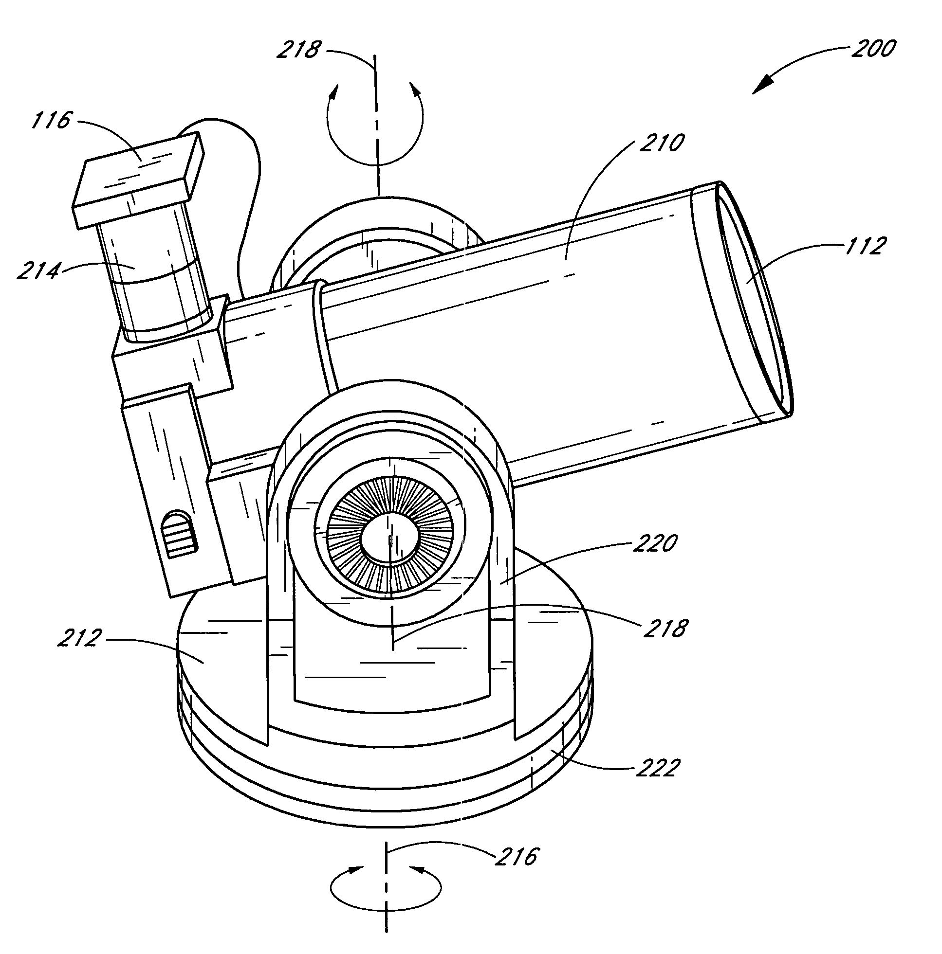
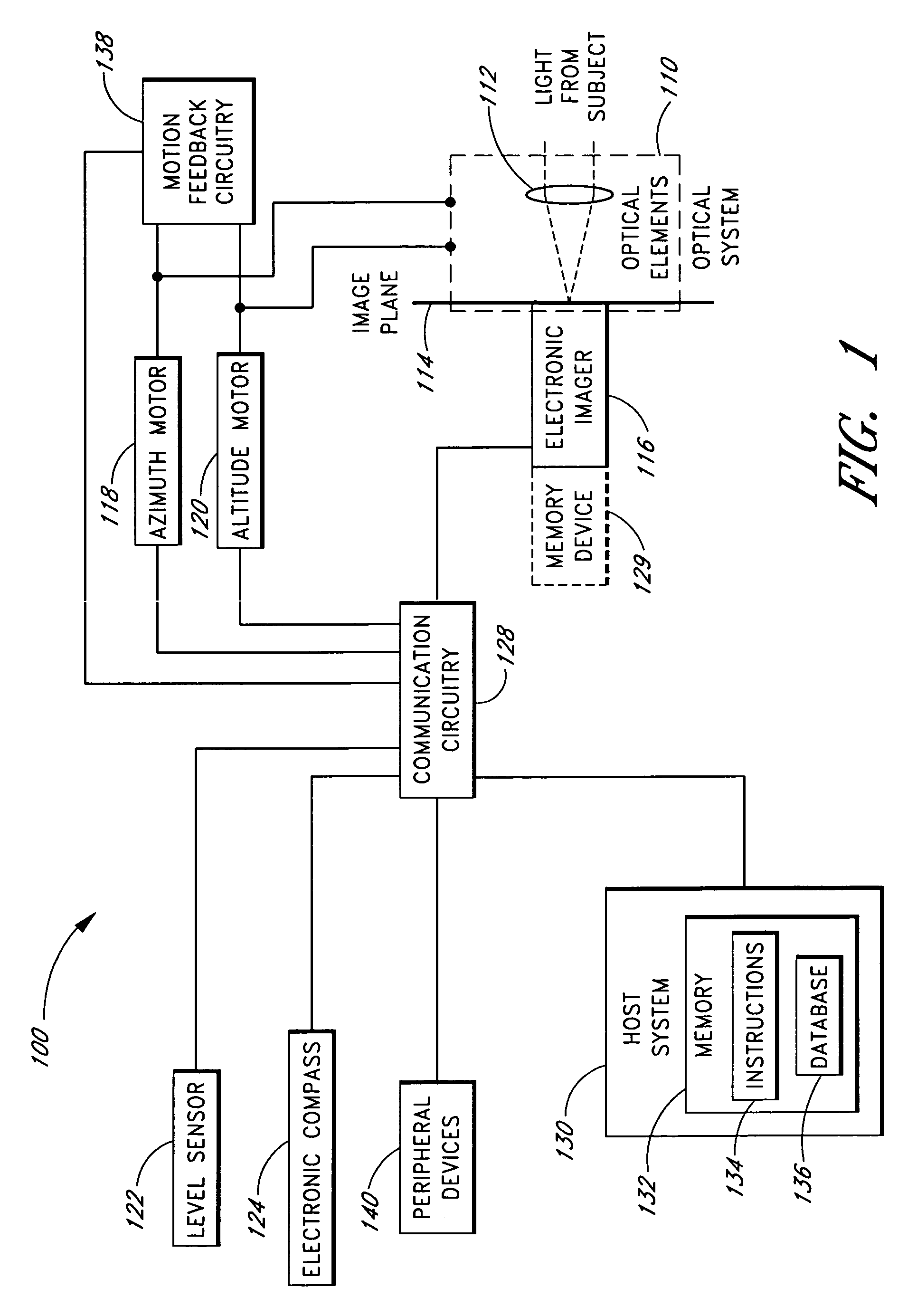
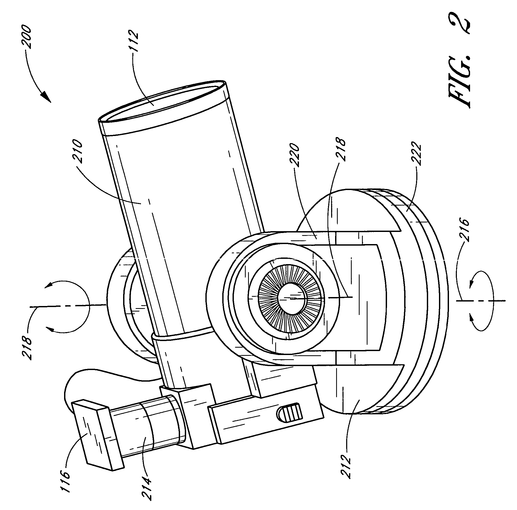
[0023]Embodiments of the present disclosure involve a telescope control system that orients a telescope with respect to the celestial sphere. To orient the telescope, certain embodiments of the telescope control system point the telescope in the direction of an alignment star or alignment area of the sky. The telescope control system images a field of view in the alignment area, and processes the images to determine the celestial coordinates of a point such as a center of the field of view the alignment area. The telescope control system then maps the telescope's coordinate system to the celestial coordinate system. Once mapped, the telescope control system can advantageously slew the telescope to any desired celestial object in the viewable sky based on, for example, user selection, system recommendations, combinations of the same, or the like.

[0024]In certain embodiments, the telescope control system seeks to improve the accuracy of the foregoing self alignment procedure. For exam...


PUM


Abstract

Embodiments of the present disclosure include self-aligning telescope control systems and self-alignment methods. In an embodiment, a telescope control system orients a telescope with respect to the celestial sphere by pointing the telescope in the direction of an alignment star or alignment area of the sky. The telescope control system images a field of view in the alignment area, and processes the images to determine the celestial coordinates of a center of the filed a field of view the alignment area. The telescope control system then maps the telescope's coordinate system to the celestial coordinate system. Once mapped, the telescope control system can advantageously slew the telescope to any desired celestial object in the viewable sky based on, for example, user selection, system recommendations, combinations of the same, or the like.

Description

REFERENCE TO RELATED APPLICATIONS[0001]The present disclosure relates to U.S. patent application Ser. No. 11 / 110,484, filed herewith titled “High Definition Telescope,” incorporated by reference herein.BACKGROUND[0002]1. Field of the Disclosure[0003]The present disclosure relates to telescope control systems and, more particularly, to systems and methods for aligning and orienting telescopes.[0004]2. Description of the Related Art[0005]The continuing evolution of low cost, high performance telescopes has decreased the complexity of finding and tracking stars, planets and other celestial objects. Thus, the popularity of amateur astronomy has increased. Some conventional telescope systems are easy to use and are capable of finding and tracking stars and other celestial bodies once they are initially oriented with the celestial sphere. However, the initial orientation is generally manual and conventional routines that align a telescope with a desired celestial object generally include ...

Claims


Application Information

Patent Timeline
Patent Type & Authority Patents(United States)
IPC IPC(8): G02B23/00
CPCG01S3/7867G02B23/00G02B23/16
Inventor BAUN, KENNETH W.HOOT, JOHN E.
Owner MEADE INSTRUMENTS
Why Eureka
Try Eureka