Plant control system

Active Publication Date: 2008-03-04
HONDA MOTOR CO LTD
View PDF9 Cites 16 Cited by
  • Summary
  • Abstract
  • Description
  • Claims
  • Application Information

AI Technical Summary

Benefits of technology

[0051]With this arrangement, the air intake volume of the internal combustion engine can be smoothly adjusted by the intake air volume adjustor. This makes it possible to prevent an actual rotational speed from overshooting a target rotational speed of the internal combustion engine or prevent the rotational speed of the internal combustion engine from significantly changing due to disturbance, thus permitting accurate control of the convergent behavior of the actual rotational speed of the

Problems solved by technology

For this reason, the convergent behavior for the difference caused by a change in a target output value and the convergent behavior for the difference cause

Method used


Image

  • Plant control system
  • Plant control system
  • Plant control system

Examples


first embodiment

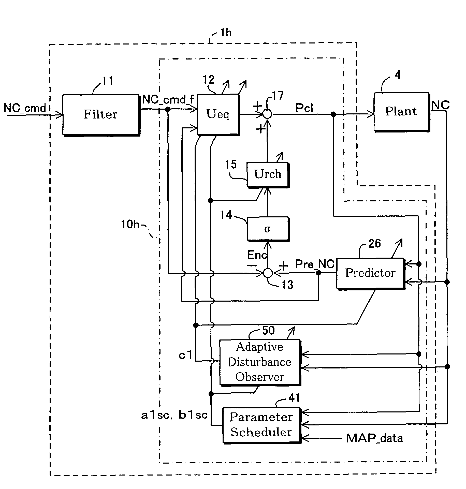
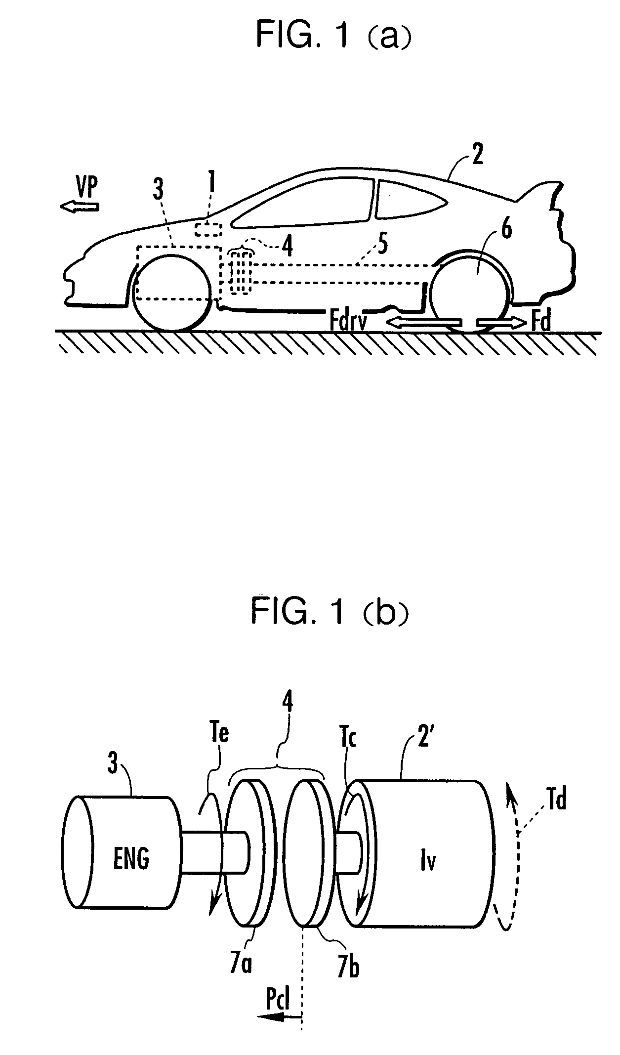
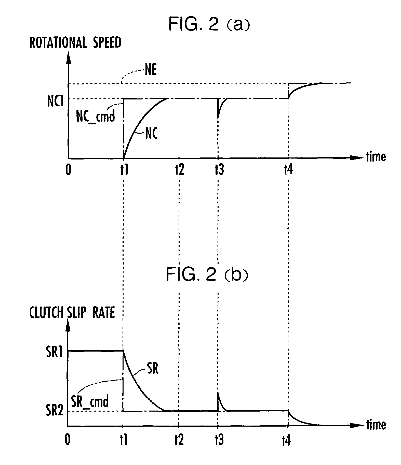
[0094]Referring to FIG. 1 to FIG. 18, a first embodiment of the present invention will be described. FIGS. 1A and 1B are block diagrams of a vehicle provided with a controller, which is a plant control system in accordance with the present invention. FIGS. 2A and 2B are explanatory diagrams of modeling of a transmission mechanism shown in FIGS. 1A and 1B. FIG. 3 is a control block diagram of a first construction example of the controller shown in FIG. 1, and FIG. 4 is a time series graph explaining an operation of the controller. FIG. 5 is a control block diagram of a second construction example of the controller shown in FIGS. 1A and 1B, and FIG. 6 is an explanatory diagram of a map prepared for determining reference parameters. FIGS. 7A and 7B are control block diagrams of a third construction example of the controller shown in FIGS. 1A and 1B. FIG. 8 is a control block diagram of a fourth construction example of the controller shown in FIGS. 1A and 1B. FIG. 9 is a control block d...

second embodiment

[0324]Referring now to FIG. 19 through FIG. 41, a second embodiment of the present invention will be described.

[0325]FIG. 19 is a construction diagram of a transmission mounted in the vehicle 2 shown in FIG. 1; FIGS. 20A and 20B are detailed diagrams of a shifting / selecting mechanism of the transmission; FIGS. 21A, 21B, 21C, and 21D are explanatory diagrams of the transmission; FIG. 22 is a construction diagram of a control unit for shifting and selecting operations that is installed in the controller 1 shown in FIG. 1; FIG. 23 is a block diagram of a selection controller shown in FIG. 22; FIGS. 24A and 24B are graphs illustrating behaviors of convergence to a target position of a shift arm during a shifting operation when a sliding mode controller of 1 degree of freedom is used; and FIGS. 25A and 25B are graphs illustrating behaviors of convergence to a target position of a shift arm during a shifting operation when a sliding mode controller of 2 degrees of freedom is used.

[0326]FI...


PUM


Abstract

A plant control system using response specifying control that makes it possible to independently set a follow-up behavior for an output value of a plant when a target output value of the plant changes and a convergent behavior for a difference between a target output value and an output value when the output value of the plant changes. The control system has a controller for determining a clutch stroke on the basis of a model equation of a clutch device such that a target rotational speed and an actual rotational speed of the clutch device coincide with each other. The controller includes a target value filter for carrying out filtering computation on a target rotational speed to calculate a filtering target value that converges to the target rotational speed with a response delay, and a response specifying control unit that determines the clutch stroke by response specifying control such that the filtering target value and the clutch rotational speed coincide with each other.

Description

BACKGROUND OF THE INVENTION[0001]1. Field of the Invention[0002]The present invention relates to a system for controlling outputs of a plant, which is to be controlled, by adopting response specifying control.[0003]2. Description of the Related Art[0004]As a system for controlling outputs of a plant, which is to be controlled, by using response specifying control, there has been proposed, for example, a throttle valve control apparatus adapted to adjust the degree of opening of a throttle valve provided in an intake passage of an engine by using sliding mode control (Japanese Laid-Open Patent Publication No. 2002-318605).[0005]The throttle valve control apparatus corrects a model parameter in a model equation of a throttle valve drive mechanism by an identifying error, i.e., a deviation from a model parameter reference value. This makes it possible to reduce a modeling error or disturbance influences in determining a manipulated variable of the throttle valve drive mechanism.[0006]I...

Claims


Application Information

Patent Timeline
IPC IPC(8): G06F17/00F16D48/06F16H61/32G05B13/04
CPCF16D48/06G05B13/04F16D2500/10412F16D2500/1045F16D2500/3026F16D2500/70442F16H61/32G05B2219/41145G05B2219/41222F16H2061/0071
Inventor YASUI, YUJISHIMOJO, KANAKO
Owner HONDA MOTOR CO LTD
Why Eureka
Try Eureka