Roll forming and punching machine for metal sheet material

a technology of metal sheet material and punching machine, which is applied in the field of punching machines, can solve the problems of material feeder, lowering manufacturing speed, and complicated operation procedur

Inactive Publication Date: 2008-03-11
CHUANG SEN JUNG
View PDF7 Cites 29 Cited by
  • Summary
  • Abstract
  • Description
  • Claims
  • Application Information

AI Technical Summary

Benefits of technology

[0003]1. Because the processing speed of the hydraulic punch 91 is relatively slower and the feeding speed of the material feeder 92 is relatively faster, a sensor must be installed in between the hydraulic punch 91 and the material feeder 92 to control the operation of the roller shape forming machine 93 subject to the punching speed of the hydraulic punch 91. This operation procedure is complicated, lowering the manufacturing speed.

Problems solved by technology

This operation procedure is complicated, lowering the manufacturing speed.2. The hydraulic punch 91 and the material feeder 92 are heavy and expensive, requiring much floor space.

Method used


Image

  • Roll forming and punching machine for metal sheet material
  • Roll forming and punching machine for metal sheet material
  • Roll forming and punching machine for metal sheet material

Examples


Embodiment Construction

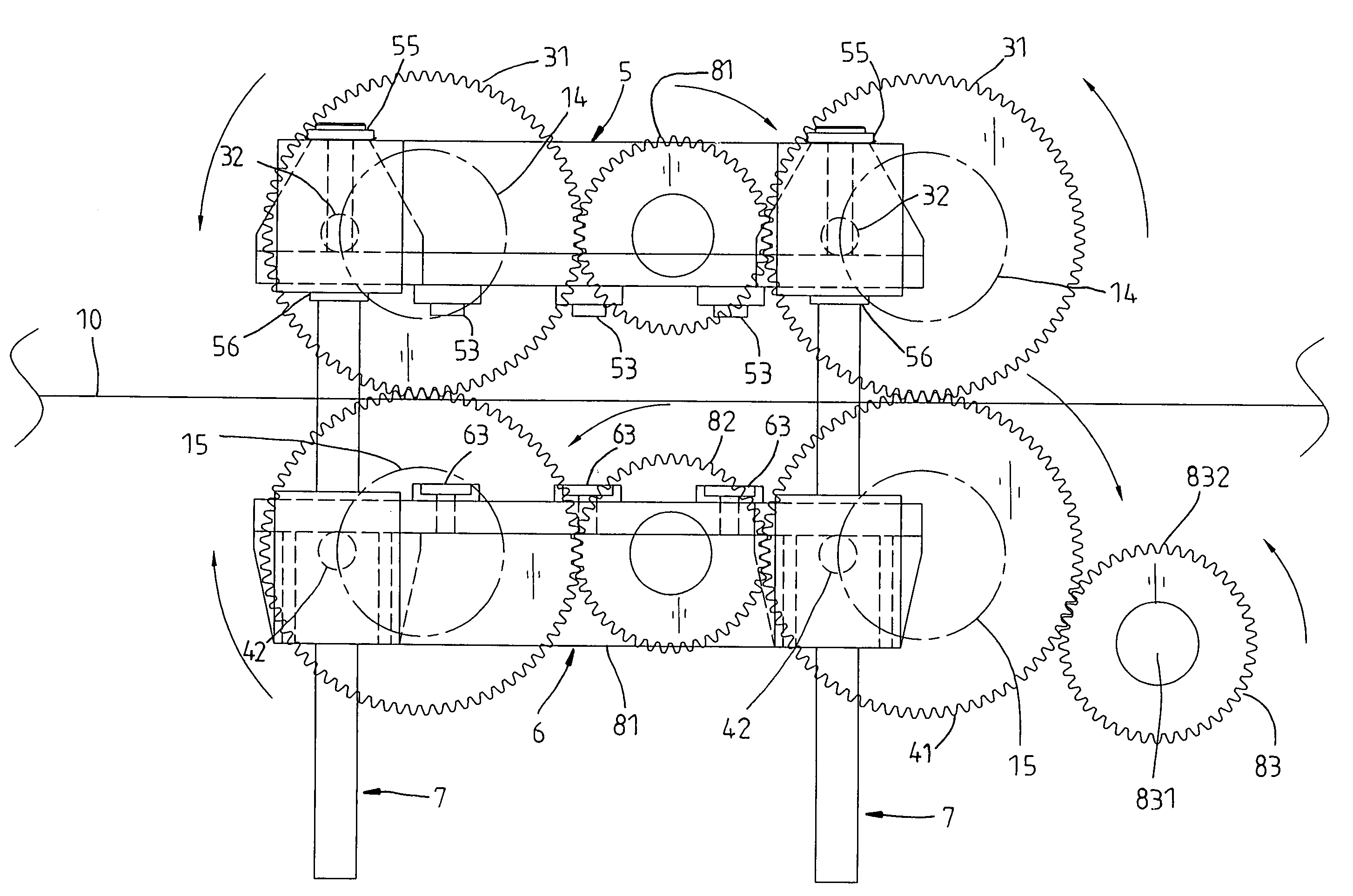
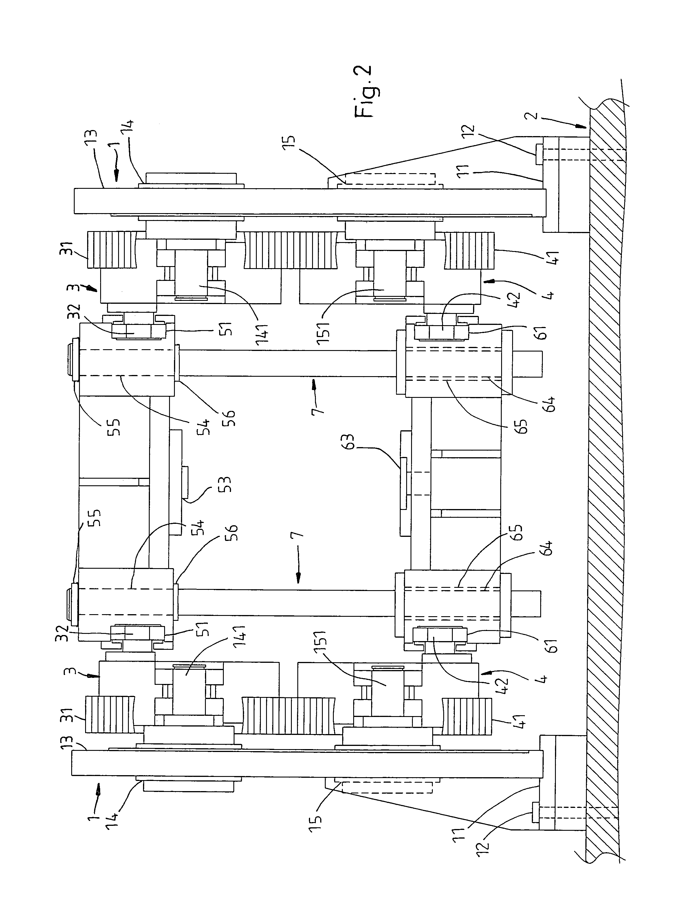
[0016]Referring to FIGS. 2˜9, a punching machine is installed in a metal working system above a roller shape forming machine (not shown), and controlled to punch holes on the metal sheet material 10 fed therein (see FIG. 10), for enabling the punched metal sheet material 10 to be further fed to the roller shape forming machine for roller-ramming into a predetermined shape.

[0017]The punching machine comprises:

[0018]Two locating frames 1 arranged in parallel on the top side of the machine base 2 of the roller shape forming machine, each locating frame 1 comprising a bottom mounting block 11 fixedly fastened to the machine base 2 of the roller shape forming machine with fasteners 12, a vertical wall 13 upwardly extending from the bottom mounting block 11 to a predetermined height, two upper supports 14 and two lower supports 15 arranged on the vertical wall 13 at different elevations (see FIG. 4), two first shafts 141 respectively horizontally provided at the upper supports 14, and two...


PUM

PropertyMeasurementUnit
elevationaaaaaaaaaa
speedaaaaaaaaaa
feeding speedaaaaaaaaaa

Abstract

A punching machine installed in the machine base of a roller shape forming machine in a metal working system and controlled to punch holes on a metal sheet material being delivered through the roller shape forming machine during operation of the roller shape forming machine. The punching action, i.e., the cycling of the closing and opening actions of the punch mold of the punching machine is set to match with the delivering speed of the metal sheet material in the roller shape forming machine so that the punching operation of the punching machine is continued during processing operation of the roller shape forming machine.

Description

BACKGROUND AND SUMMARY OF THE INVENTION[0001]The present invention relates to a punching machine and more particularly, to such a punching machine, which is installed in the machine base of a roller shape forming machine in a metal working system and controlled to punch holes on a metal sheet material being delivered through the roller shape forming machine during operation of the roller shape forming machine.[0002]In a metal working system, as shown in FIG. 1, metal sheet material 90 is fed to a hydraulic punch 91 and punched by the hydraulic punch 91 to have holes at desired locations, and then the punched metal sheet material 90 is carried by a material feeder 92 to a roller shape forming machine 93 and rammed into the desired shape. This metal working system is still not satisfactory in function because of the following drawbacks:[0003]1. Because the processing speed of the hydraulic punch 91 is relatively slower and the feeding speed of the material feeder 92 is relatively fast...

Claims


Application Information

Patent Timeline
Patent Type & Authority Patents(United States)
IPC IPC(8): B21D43/28
CPCB21D28/26B21D43/02Y10T83/4786
Inventor CHUANG, SEN-JUNG
Owner CHUANG SEN JUNG
Why Eureka
Try Eureka