Stretch forming method for a sheet metal skin segment having compound curvatures

a stretch forming and segment technology, applied in aircraft components, transportation and packaging, etc., can solve the problems of difficult manufacturing of noselips, high cost, and high cost of drawing dies used in drawing forming processes

Active Publication Date: 2008-03-11
ROHR INC
View PDF52 Cites 11 Cited by
  • Summary
  • Abstract
  • Description
  • Claims
  • Application Information

AI Technical Summary

Problems solved by technology

The compound curved shape of the noselip, the noselip's large depth-to-diameter ratio, and the large overall diameter of a noselip for high bypass ratio aircraft engines (up to 10 feet in diameter) can make the noselip particularly difficult to manufacture.
Unfortunately, the draw forming process is complex and time consuming.
In addition, the draw dies used in the draw forming process experience substantial wear, and require periodic refurbishment or replacement.
Furthermore, the tooling and equipment required to draw form a nacelle noselip, for example, can be expensive to purchase and costly to maintain.
Unfortunately, the equipment and tooling required to spin form a part as large as a nacelle noselip can be expensive to purchase, and costly to maintain.

Method used


Image

  • Stretch forming method for a sheet metal skin segment having compound curvatures
  • Stretch forming method for a sheet metal skin segment having compound curvatures
  • Stretch forming method for a sheet metal skin segment having compound curvatures

Examples


first embodiment

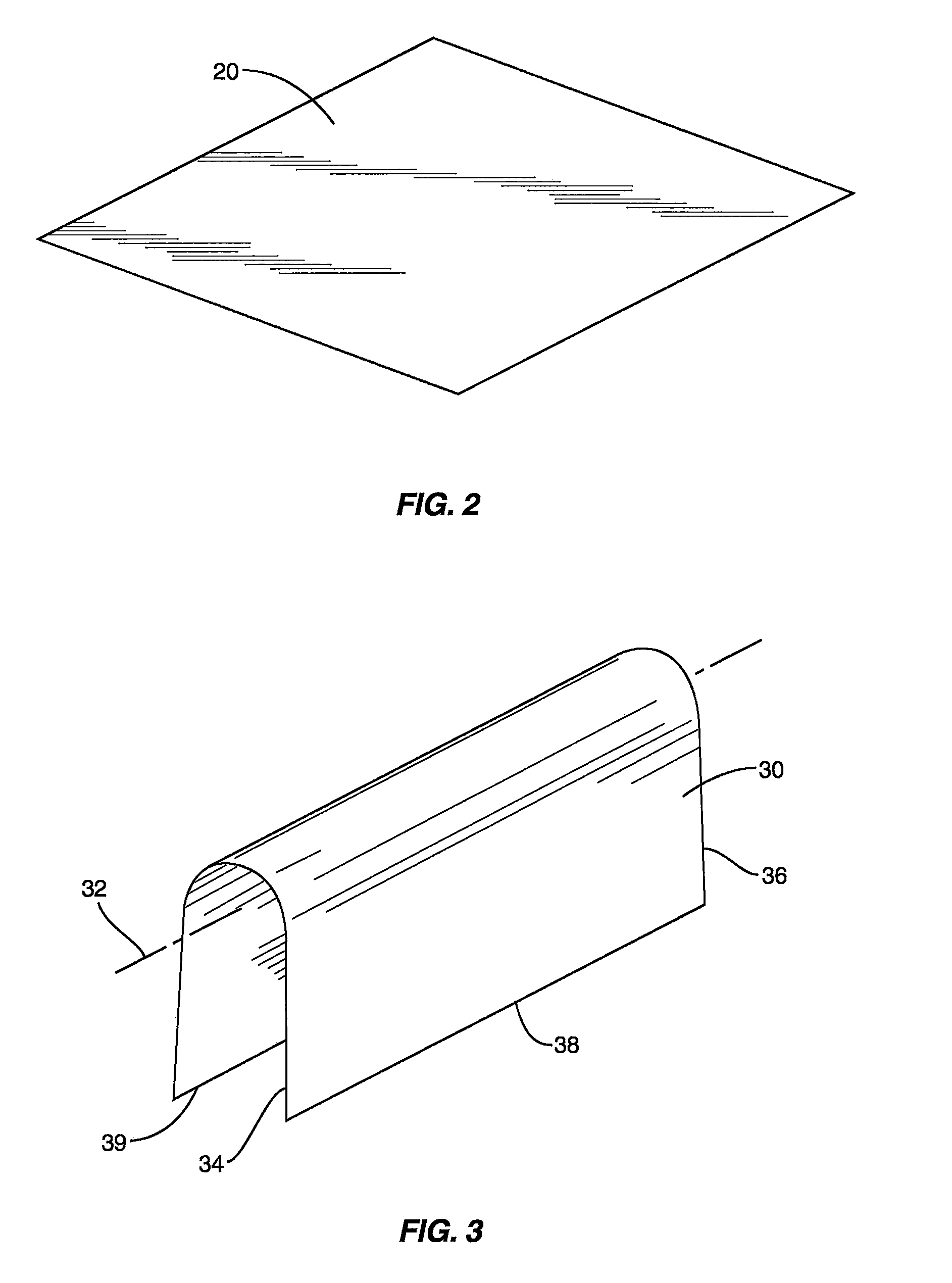
[0028]The U-shaped workpiece 30 is placed over a flexible pre-form mandrel 40, 50, 60 as shown in FIG. 4. As used herein, the terms “flexible” and “bendable” are used interchangeably to mean being capable of flexing or bending in at least one direction without substantial permanent deformation or breakage. Various embodiments 40, 50, 60 of the flexible pre-form mandrel are shown in FIGS. 5-7. As shown in FIG. 5, the flexible pre-form mandrel 40 is an elongated member having a curved upper surface 42 and substantially flat ends 44, 46. The curved upper surface 42 curves about a spanwise or longitudinal axis 48. The curvature of the upper surface substantially corresponds to the desired chordwise curvature of a finally formed nacelle noselip 10. The pre-form mandrel 40 preferably is constructed of a flexible and substantially incompressible material. As used herein, the term “incompressible” is used to refer to a material that substantially maintains its original thickness when subjec...

third embodiment

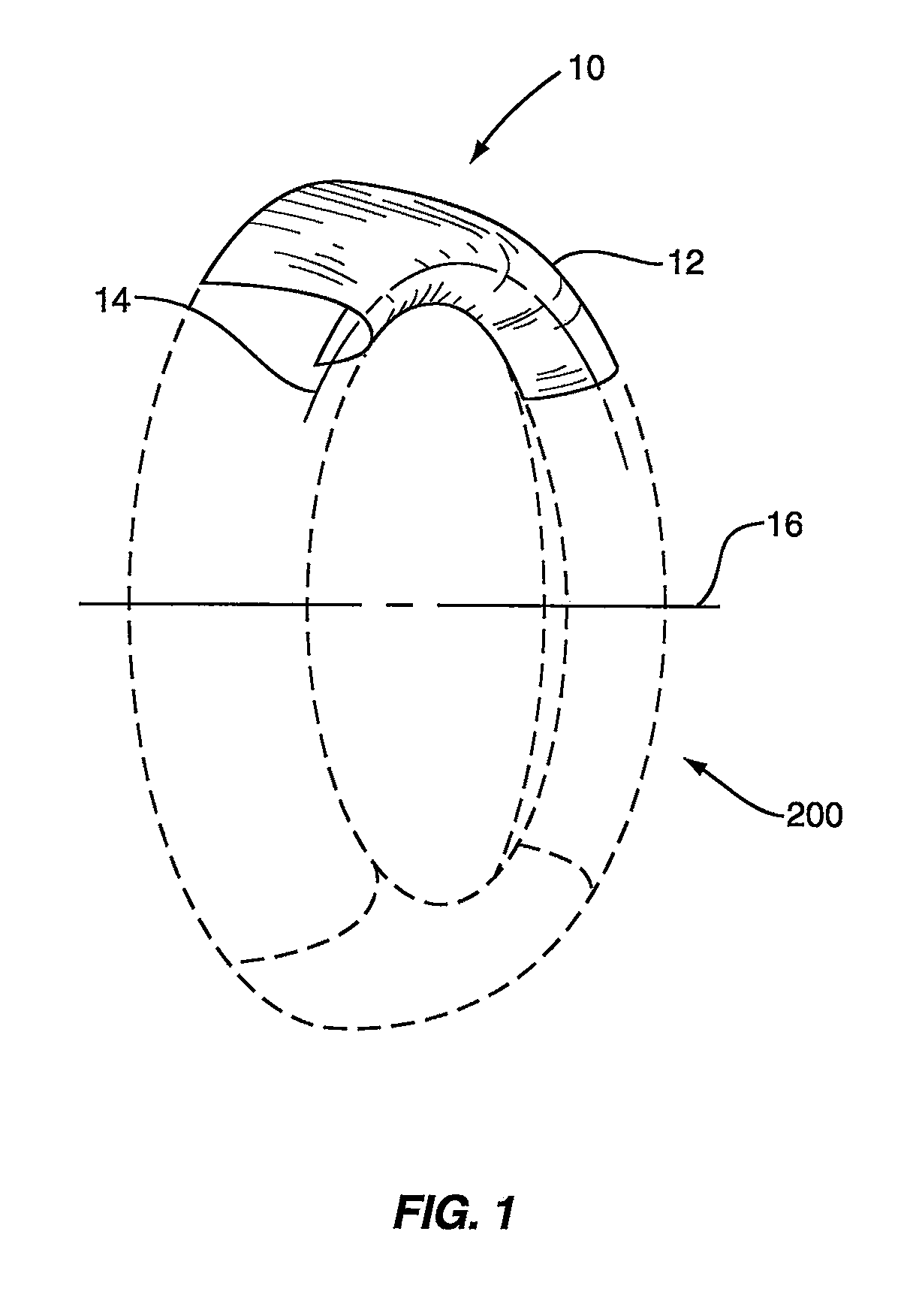
[0030]a pre-form mandrel for use in a process according to the invention is shown in FIGS. 7A and 7B. As shown in an unrestrained state in FIG. 7A, the pre-form mandrel 60 is similar to the non-segmented mandrel 40 described above, but has a spanwise curvature around a chordwise axis 62. In the unrestrained state shown in FIG. 7A, the upper surface 64 of the pre-form mandrel 60 substantially corresponds in shape to a finally formed nacelle noselip 10, like that shown in FIG. 1. The mandrel 60 is constructed of a flexible and substantially incompressible material such as polyurethane. The flexible material permits the mandrel 60 to be restrained in a straightened condition (like that shown in FIG. 7B). In this restrained condition, the mandrel 60 is substantially identical in shape to the non-segmented mandrel 40 described above.

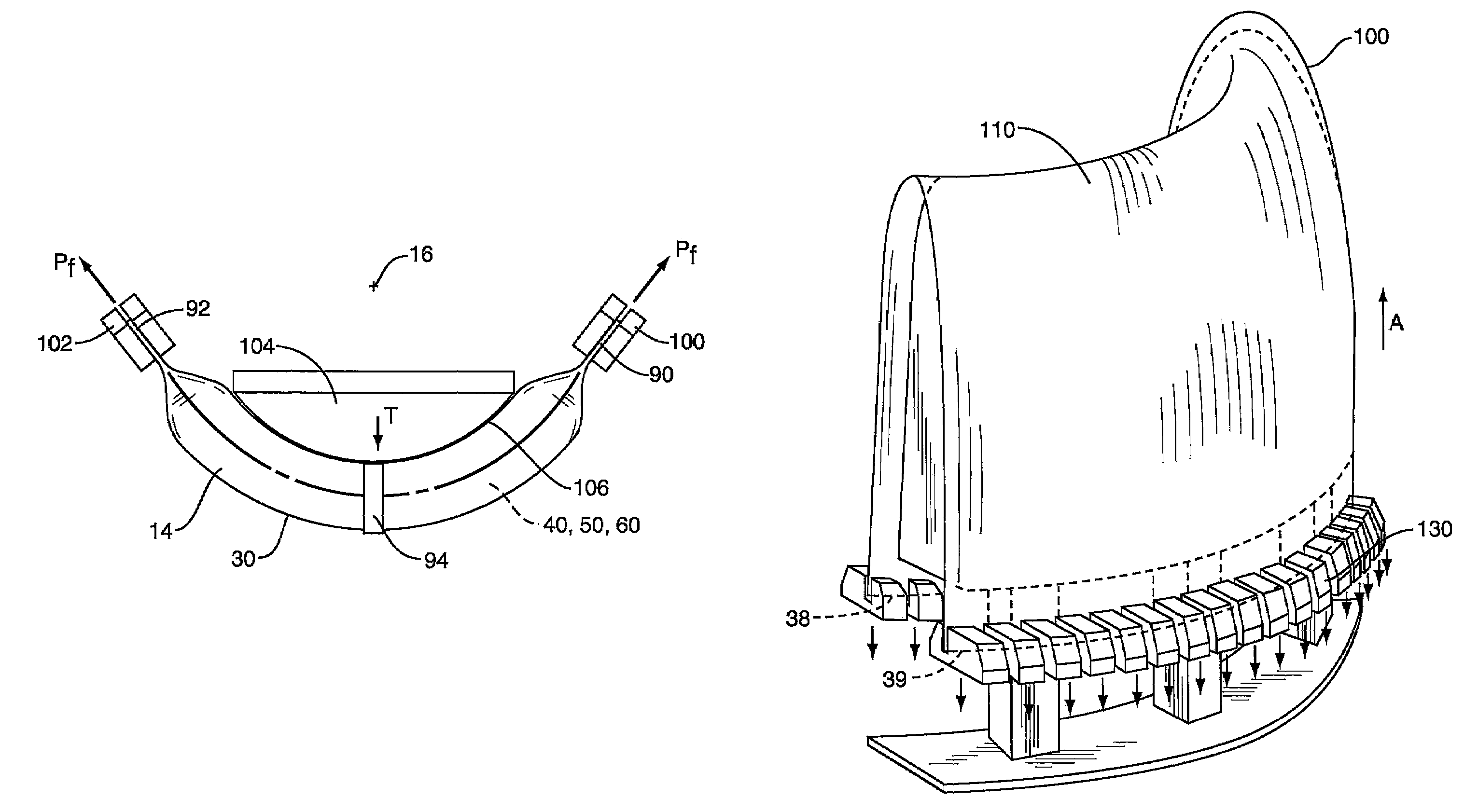
[0031]As shown in FIG. 9, in a preferred embodiment of a process according to the invention, the ends 34, 36 of the workpiece 30 are crimped to form substant...


PUM

PropertyMeasurementUnit
diameteraaaaaaaaaa
thicknessaaaaaaaaaa
thicknessaaaaaaaaaa

Abstract

A method of forming an aircraft nacelle nose lip segment. The method includes bending a sheet of metal into a substantially U-shaped workpiece having a spanwise axis, opposed first and second ends, and opposed first and second edges. The method further includes placing the workpiece over a substantially flexible first mandrel, stretching the workpiece in a spanwise direction between the first and second ends, and wrapping the workpiece and first mandrel together about a curved die while stretching the workpiece. The workpiece is thereby plastically deformed to have a first shape. The method may further include removing the workpiece from the first mandrel, and placing the workpiece over a substantially rigid second mandrel that substantially corresponds in shape to the first shape of the workpiece. The workpiece is stretched over the second mandrel in a chordwise direction that is substantially transverse to the spanwise axis of the workpiece, thereby further plastically deforming the workpiece.

Description

FIELD OF THE INVENTION[0001]The invention relates to methods of producing sheet metal skins having compound curvilinear shapes and large depth-to-diameter ratios, and more particularly relates to a method of stretch forming a segment of an aircraft engine nacelle inlet nose lip.BACKGROUND[0002]Aircraft engine nacelles provide streamlined enclosures for aircraft engines. The nacelles typically include an underlying support structure covered by a thin, aerodynamically shaped metal skin. The portion of the nacelle that surrounds an engine's inlet commonly is referred to as the nacelle inlet nose lip, or simply the noselip. The noselip has a complex shape with compound curvatures. First, the noselip has a chordwise curvature that curves from forward portions of the noselip toward aft portions of the noselip, thereby forming an aerodynamic shape. In addition, the noselip has a spanwise curvature that curves in a circumferential direction around the inlet. The noselip has a relatively lar...

Claims


Application Information

Patent Timeline
Patent Type & Authority Patents(United States)
IPC IPC(8): B21D11/02
CPCB21D25/02B21D53/92
Inventor STEWART, JOHN R.
Owner ROHR INC
Why Eureka
Try Eureka