
Oxygen supply system having a central flow control unit

a flow control and oxygen supply technology, applied in the direction of operating means/releasing devices of valves, functional valve types, respirators, etc., can solve the problems of requiring power during operation, affecting the operation efficiency of the system, and so as to improve the oxygen supply and simplify the system. , the effect of reducing the amount of electrical power required

Active Publication Date: 2008-03-11
CARLETON TECH
View PDF28 Cites 5 Cited by
  • Summary
  • Abstract
  • Description
  • Claims
  • Application Information

AI Technical Summary

Benefits of technology

"The patent describes a system for supplying oxygen to passengers in an emergency situation on an aircraft. The system is controlled by a central control valve unit that automatically charges the distribution lines with oxygen and then operates without needing further electrical power. The amount of oxygen a passenger requires depends on their altitude, so the system provides a two-phase supply increase at higher altitudes. This system simplifies the oxygen supply system and ensures that passengers are supplied with oxygen quickly and efficiently in an emergency situation."

Problems solved by technology

U.S. Pat. No. 6,244,540 issued to Stabile teaches a method for calculating the oxygen required after emergency cabin decompression, but is a relatively complex system that provides constant monitoring of altitude.
U.S. Pat. No. 5,709,204 issued to Lester discloses a specially designed escape mask, but does not recognize the problem of cabin depressurization and the need to charge the system quickly with oxygen using a pneumatic control system.
This system is complex and requires power during operation.

Method used


Image

  • Oxygen supply system having a central flow control unit
  • Oxygen supply system having a central flow control unit
  • Oxygen supply system having a central flow control unit

Examples


Embodiment Construction

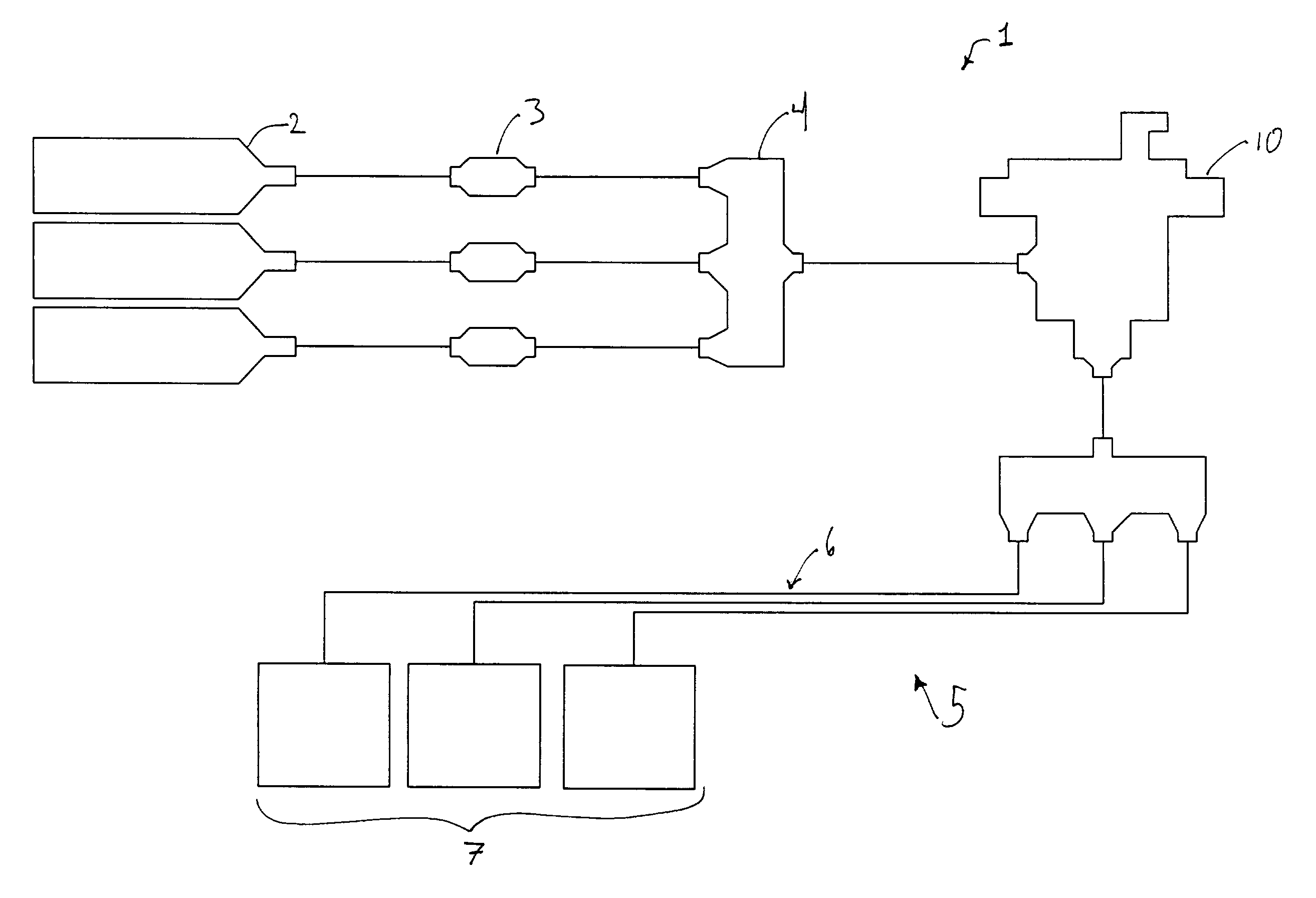
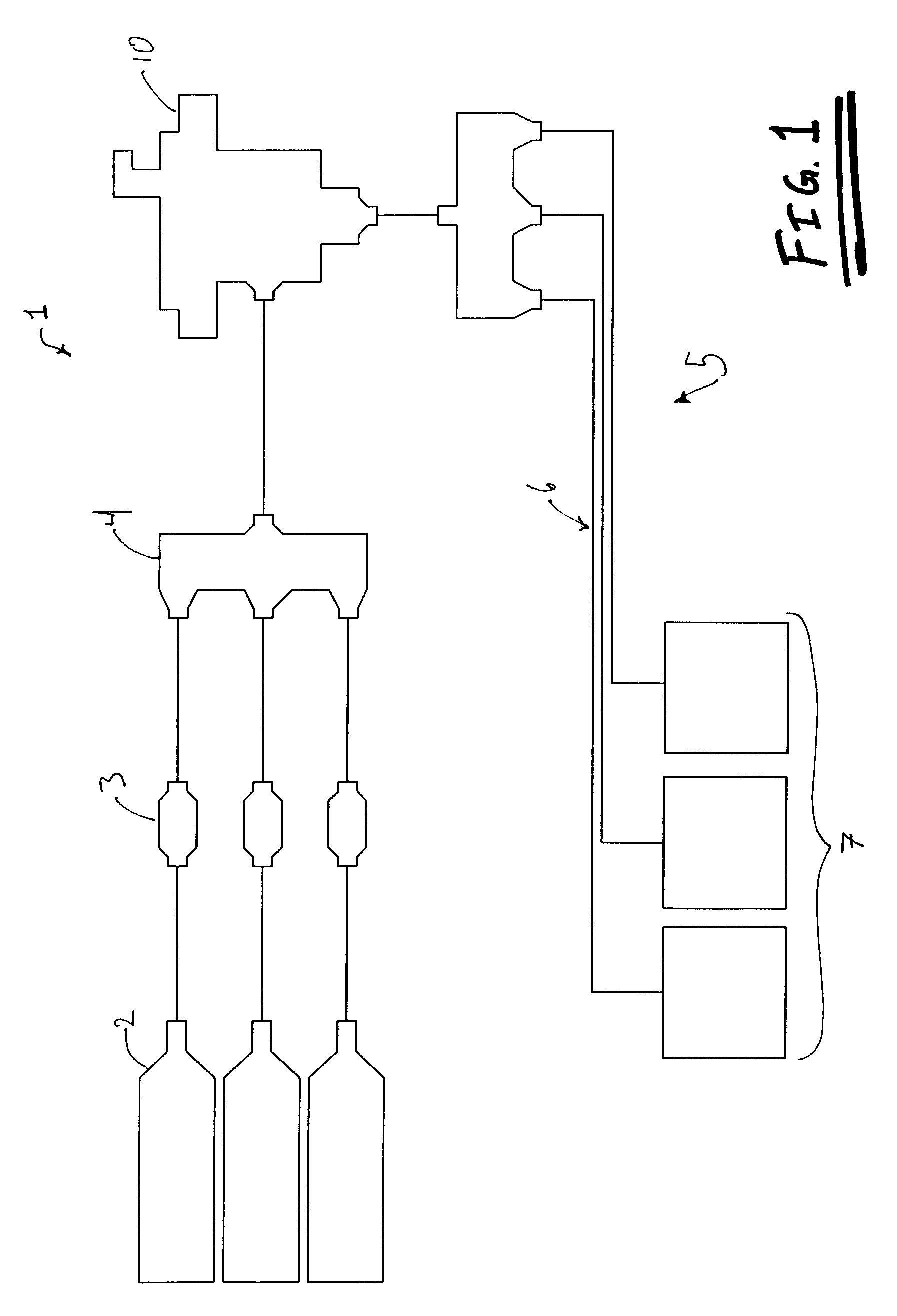
[0021]Referring now to FIG. 1, an emergency oxygen supply system (1) for a passenger aircraft has an oxygen supply, usually in the form of multiple bottles (2) of highly pressurized oxygen that are stepped down to through regulators (3) to pressures of 115-125 pounds per square inch. Oxygen is then fed through a manifold (4) to a central flow control valve (10) that controls the charging and supply of the distribution system (5) of oxygen to passengers. The distribution system has multiple lines (6) that provide emergency oxygen to multiple individual user stations (7). These user stations typically are drop down masks that are deployed in the case of emergency and can be used by each individual passenger.

[0022]The CFCV (10) is kept inactive until activated by either a person or an automatic sensor. Then the CFCV (10) operates to provide a full pressure purge of the distribution lines (6) in order to replace the ambient air with oxygen. Typically the purge is done by allowing relati...


PUM


Abstract

The present invention is a centralized flow control unit (CFCU) for regulating oxygen flow in a multiple user emergency oxygen distribution system in passenger aircraft. Upon activation, the CFCU initially allows unregulated flow of oxygen to surge into the distribution system to thereby purge the ambient air out of the system. After a sufficient pressure is achieved in the distribution system, the CFCU regulates the flow mechanically with a diaphragm engaging a regulator valve. The pressure of the oxygen under the diaphragm causes the regulator valve to reduce the flow of the oxygen through the CFCU. The CFCU accounts for changes in altitude by including a bleed passageway in the diaphragm. A small amount of the oxygen under the diaphragm bleeds to the chamber above the diaphragm then a bleed exit allows the oxygen to escape to the ambient air. An aneroid valve in fluid communication with the bleed exit linearly adjusts the amount of oxygen allowed to exit through the bleed exit such that less oxygen is allowed to escape for an increase in altitude. Thus the pressure above the diaphragm increases to thereby allow more oxygen to flow through the regulator valve.

Description

FIELD OF INVENTION[0001]This application relates to oxygen flow control systems for emergency oxygen supply systems in passenger aircraft.BACKGROUND[0002]Emergency oxygen supply systems for passenger aircraft are well known and characterized by being able to provide to each passenger a supply of oxygen in the case of an emergency. These systems are designed to be used during cabin depressurization and thus are intended to supply each passenger with a sufficient oxygen flow to meet the physiological requirements for high-altitude survival.[0003]In the past the main emphasis in development has been directed towards improved breathing apparatus, improved oxygen generation, or accurate delivery of oxygen to meet physiological requirements.[0004]U.S. Pat. No. 6,244,540 issued to Stabile teaches a method for calculating the oxygen required after emergency cabin decompression, but is a relatively complex system that provides constant monitoring of altitude.[0005]U.S. Pat. No. 5,709,204 iss...

Claims


Application Information

Patent Timeline
Patent Type & Authority Patents(United States)
IPC IPC(8): F16K17/36A61M16/00A62BA62B7/14
CPCA62B7/14Y10T137/2012Y10T137/7734
Inventor TALTY, JAMES
Owner CARLETON TECH
Learn More