Fastener and method for reducing stress failure in an engine component

a technology of internal combustion engine and stress failure, which is applied in the direction of screws, washers, ways, etc., can solve the problems of high torque, significant clamping load, and high torquing of fasteners, so as to reduce the radius, reduce the stress failure of internal combustion engine components, and increase the load carrying capacity of at least a portion of threaded interfaces

Inactive Publication Date: 2008-03-11
CUMMINS INC
View PDF27 Cites 1 Cited by
  • Summary
  • Abstract
  • Description
  • Claims
  • Application Information

AI Technical Summary

Benefits of technology

[0009]In view of the foregoing, an advantage of the present invention is in providing a threaded fastener for specifically reducing stress failures in a fastening joint of an internal combustion engine.
[0010]In accordance with one aspect of the present invention, a fastener joint that reduces stress failure in an internal combustion engine component is provided. In one embodiment, the fastener joint includes a threaded hole in the internal combustion engine component, and a threaded fastener having a threaded tip portion with a radius and a distal end. The threaded tip portion is inserted into the threaded hole of the internal combustion engine component to engage the threaded hole, and define a threaded interface between the threaded hole and the threaded tip portion. In accordance with the present invention, the threaded fastener includes a stress reduction means for increasing the load carrying capability of at least a portion of the threaded interface.
[0011]In one embodiment of the fastener joint, the stress reduction means includes progressive reduction of the radius of at least a part of the threaded tip portion. In this regard, the radius may be progressively reduced to the distal end of the threaded tip portion. In one implementation, approximately 3 to 10 threads of the threaded tip portion from the distal end have reduced radius.
[0012]In accordance with another embodiment of the fastener join, the stress reduction means includes an axially extending hole at the distal end having a progressively reduced diameter away from the distal end. In this regard, the largest diameter of the hole may be positioned at the distal end. In one implementation, the largest diameter of the hole is approximately 35-60% of a major diameter of the threaded fastener, and the hole as a depth dimension of approximately 60-110% of a major diameter of the threaded fastener.
[0013]Still another aspect of the present invention is in providing a fastener that reduces stress failure of a fastening joint of an internal combustion engine component. In one embodiment, the fastener includes an elongated shank, and a threaded tip portion on the elongated shank with a radius and a distal end. The threaded tip portion at least partially defines a threaded interface when in use, and the radius of at least a part of the threaded tip portion is progressively reduced toward the distal end. In one embodiment, approximately 3 to 10 threads of the threaded tip portion from the distal end have reduced radius.
[0014]In another embodiment, the fastener includes a threaded tip portion with an axially extending hole at the distal end having a progressively reduced diameter away from the distal end. In one embodiment, the largest diameter of the hole is approximately 35-60% of a major diameter of the threaded fastener, and the hole as a depth dimension of approximately 60-110% of a major diameter of the threaded fastener.

Problems solved by technology

Many fasteners are subjected to high torque to tightly secure internal combustion engine components together, and are subjected to significant clamping loads.
In both of these applications, high torquing of the fasteners is required to establish high clamping loads, and the fasteners are subjected to high cyclical loads caused by the operation of the internal combustion engine.
After long periods of use, it has been found that stress crack and joint failure can occur in the internal combustion engine components at these locations.
In this regard, such failures have been found especially when the fastener joint is subjected to additional stress.
Such increase in cylinder pressures of internal combustion engine has been found to cause stress cracks at the threads engaged by the main bearing.
If such stress cracking and joint failure occurs in the engine block, the repair can be extremely expensive.
Therefore, there exists an unfulfilled need for a method for reducing stress failures at fastening joints in an internal combustion engine that can be caused by cyclical loading of highly torqued fasteners when cylinder pressures are increased.

Method used


Image

  • Fastener and method for reducing stress failure in an engine component
  • Fastener and method for reducing stress failure in an engine component
  • Fastener and method for reducing stress failure in an engine component

Examples


Embodiment Construction

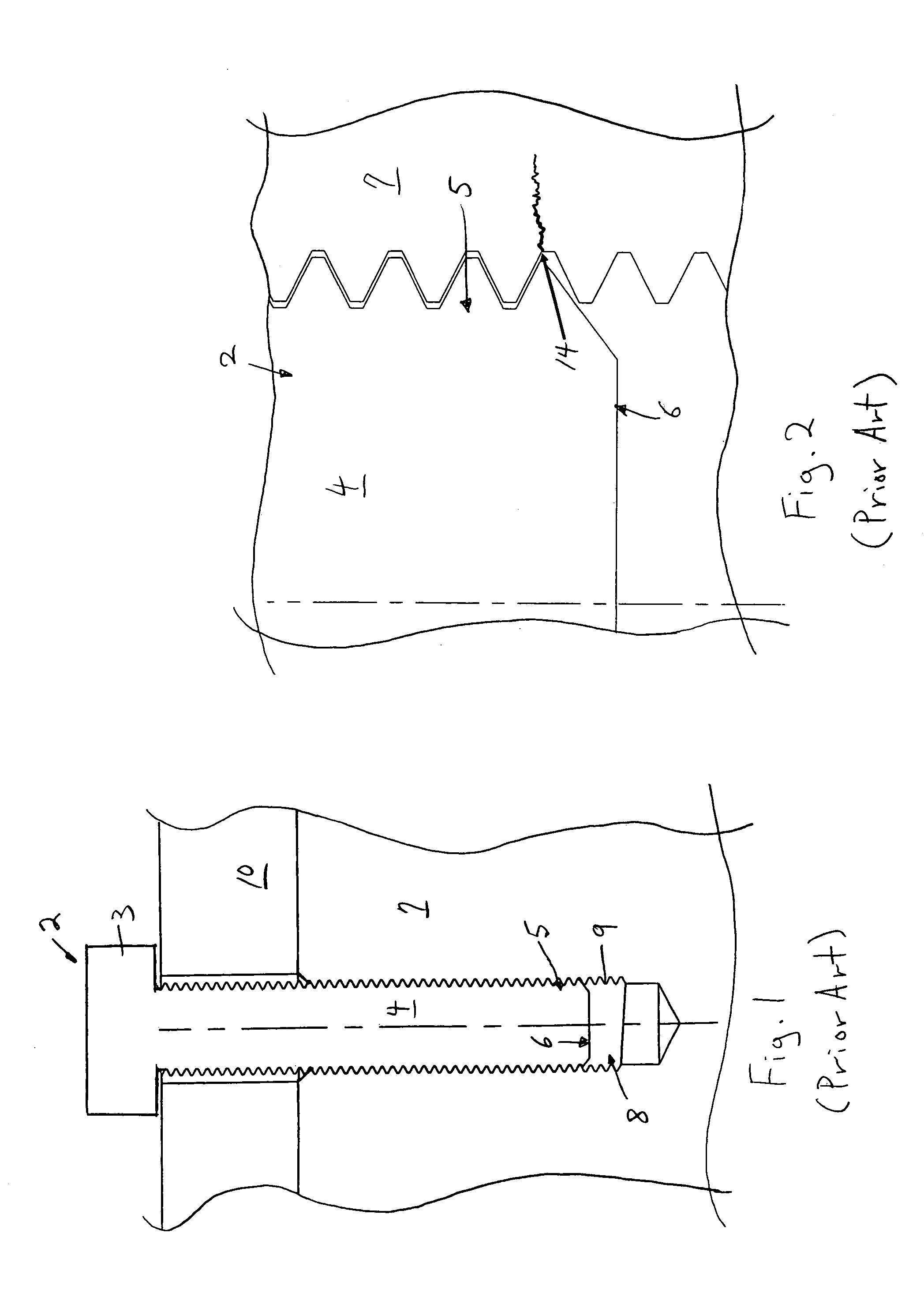
[0026]FIG. 1 shows a cross-sectional view of a prior art threaded fastener 2 that is used in an internal combustion engine. As can be appreciated, the threaded fastener 2 is a bolt. The threaded fastener 2 is used to secure two components of an internal combustion engine together, for example, to secure a cylinder head 10 to the engine block 7 in FIG. 1. As can be seen, the threaded fastener 2 includes a head 3, a shank 4, and a threaded tip portion 5 which terminates at a distal end 6. The threaded tip portion 5 is inserted into a threaded hole 8 that is provided in the internal combustion engine component, for example, the engine block 7 shown. The threaded hole 8 includes threads 9 that are engaged by the threaded tip portion 5 of the threaded fastener 2, thereby defining a threaded interface between the threaded tip portion 5, and the threaded hole 8.

[0027]By tightening the threaded fastener 2 into the threaded hole 8, the cylinder head 10 is securely clamped to the engine block...


PUM


Abstract

A fastener and a method for reducing stress failure in a fastening joint of an internal combustion engine component are provided. The threaded fastener may be a bolt or a stud secured to an engine block. The fastener has a threaded tip portion with a radius and a distal end. The threaded tip portion is inserted into a threaded hole to define a threaded interface. In one embodiment, the load carrying capability is increased by progressively reducing the radius of at least a part of the threaded tip portion. In another embodiment, the load carrying capability is increased by an axially extending hole at the distal end of the threaded tip portion, the hole having a progressively reduced diameter.

Description

BACKGROUND OF THE INVENTION[0001]1. Field of the Invention[0002]The present invention is directed to a fastener, fastener joint, and a method for reducing stress in an internal combustion engine component.[0003]2. Description of Related Art[0004]Various designs for threaded fasteners are known for addressing different problems associated with fasteners. For example, U.S. Pat. No. 4,973,209 to Essom et al. discloses a screw for use in contaminated pre-tapped holes. The reference discloses a locking screw having a head at one end, a special entry portion at the other end, and a trilobular shank portion extending from the entry portion toward the head. The screw is disclosed as having a thread profile that is of a double angle configuration, and having an entry section that is tapered and formed with a series of truncations which serve to clear progressively, a contaminating coating in an internally threaded workpiece, such as a nut.[0005]U.S. Pat. No. 6,120,227 to Murase et al. disclo...

Claims


Application Information

Patent Timeline
Patent Type & Authority Patents(United States)
IPC IPC(8): F16B35/00
CPCF16B35/044
Inventor RAUB, JONATHAN H.TICKEL, ROBERT G.STORKMAN, WILLIAM R.
Owner CUMMINS INC
Why Eureka
Try Eureka