
Wireless remote monitoring system

a monitoring system and wireless technology, applied in the field of monitoring systems, can solve the problems of laborious, difficult, and expensive task of multiple site visits in multiple locations

Active Publication Date: 2008-03-11
HACH CO
View PDF6 Cites 28 Cited by
  • Summary
  • Abstract
  • Description
  • Claims
  • Application Information

AI Technical Summary

Benefits of technology

[0005]In accordance with the present invention there is provided a wireless remote monitoring system which enables a person to collect data from and monitor the status of flow meters and scientific instruments in remote locations by means of the GSM cellular telephone network using a modem connected to a personal computer.

Problems solved by technology

Multiple site visits in numerous locations is a challenging, labor intensive, and expensive task.

Method used


Image

  • Wireless remote monitoring system
  • Wireless remote monitoring system
  • Wireless remote monitoring system

Examples


Embodiment Construction

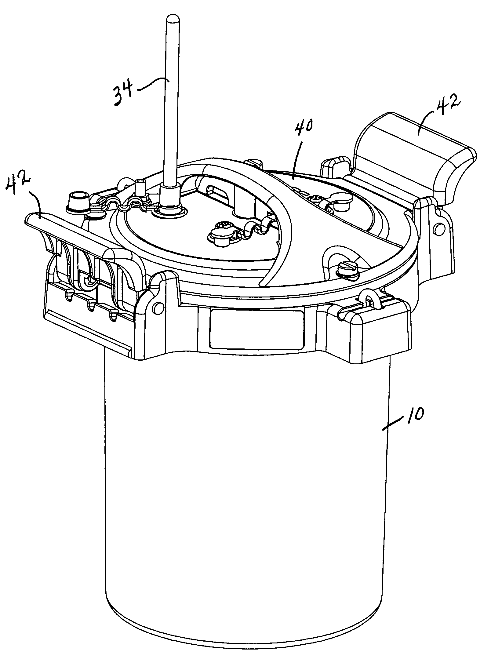
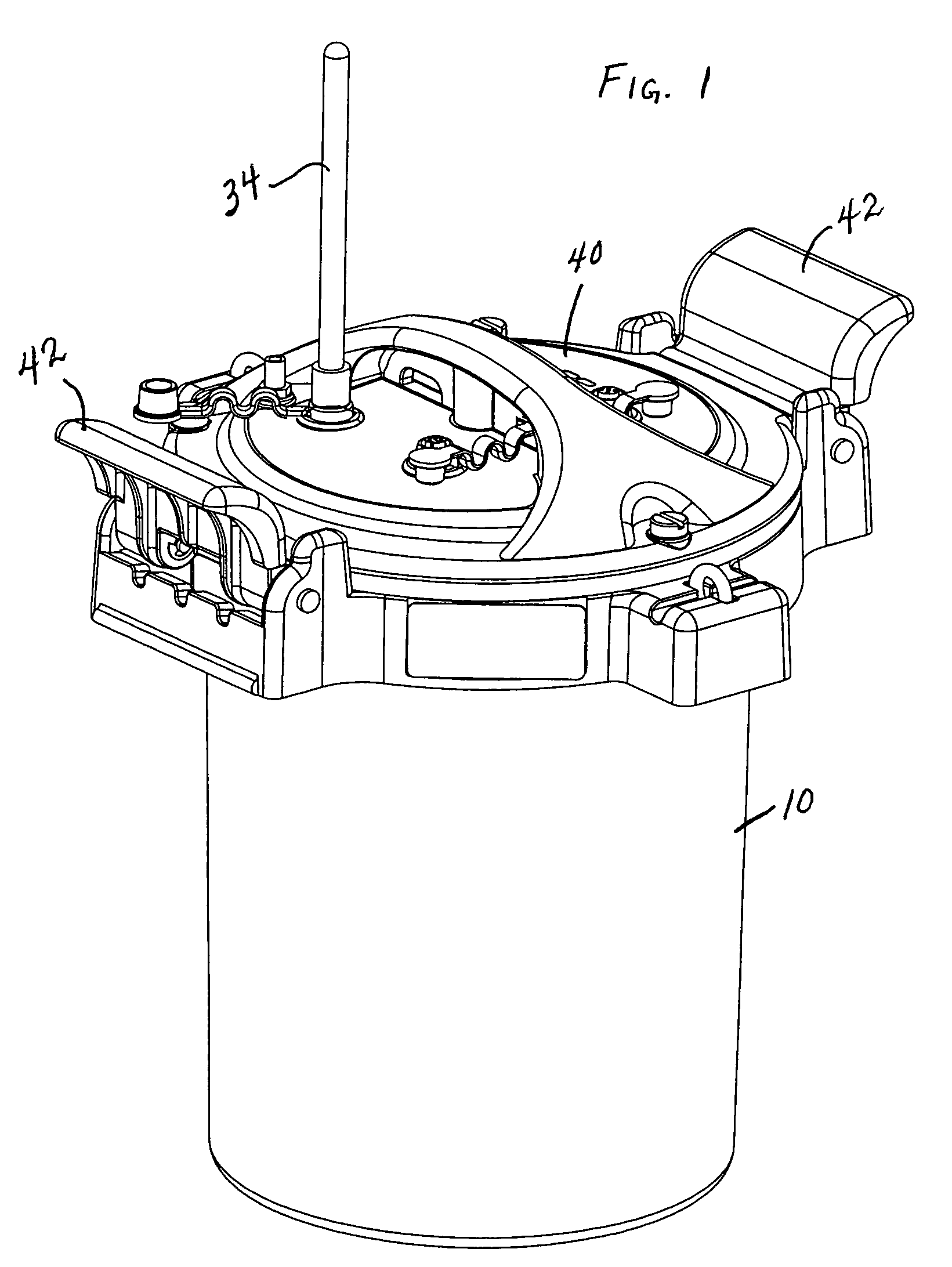
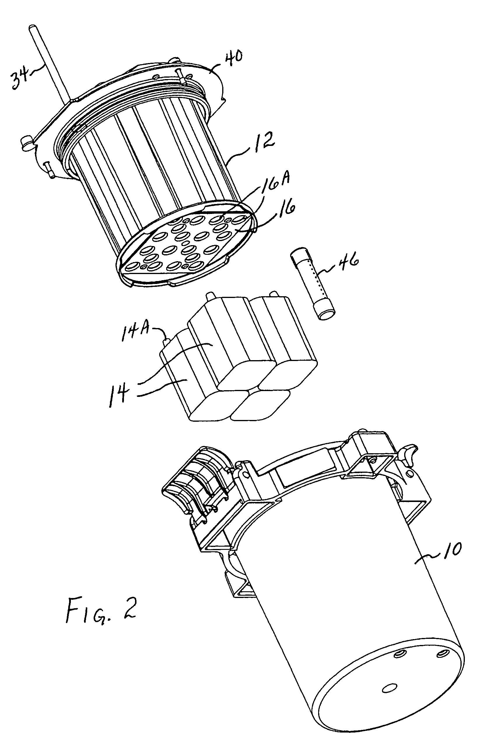
[0020]In the drawings there is shown a preferred embodiment of the wireless remote monitoring system of the invention. Preferably there is an outer housing section 10 and an inner housing section or module 12 which fits within the outer housing. The purpose of the inner housing section is to protect the electronics when the outer housing is opened for battery replacement.

[0021]Batteries 14 are contained within the outer housing section and include upwardly projecting terminals 14A and 14B. The negative terminal 14B is located in the center of each battery. The bottom of the inner housing section 12 includes a plate 16 with a plurality of openings 16A through which the battery terminals may project in order to make electrical contact with a battery board 18. The battery board facilitates interconnection of the four alkaline 6V batteries to the wireless GSM cellular modem 28 and the central processing unit 30. Of course, instead of using batteries, it is possible to use external auxil...


PUM


Abstract

A remote monitoring system is described which enables monitoring of flow meters or other scientific instruments from a remote location using the GSM cellular phone network. The system includes a wireless modem utilizing the GSM cellular phone network, a central processing unit, connection of a scientific instrument to the central processing unit, power supply (e.g. one or more batteries), and an enclosure for housing the components.

Description

CROSS-REFERENCE TO RELATED APPLICATION[0001]This application is based upon, and claims priority from, our Provisional Application No. 60 / 474,966, filed Jun. 2, 2003.FIELD OF THE INVENTION[0002]This invention relates to monitoring systems. More particularly, it relates to systems for monitoring and controlling flow meters and other scientific instruments from a remote location.BACKGROUND OF THE INVENTION[0003]Flow meters and other scientific instruments are widely used in many remote locations for a variety of purposes (e.g. to monitor flow rates of water in sewer systems). It is necessary for workmen to physically visit the remote sites to monitor the flow meters or other instruments (e.g. samplers) to gather data. Multiple site visits in numerous locations is a challenging, labor intensive, and expensive task. Ensuring that each site is operational and that maintenance is regularly scheduled is necessary to guarantee accurate and reliable data.[0004]There has not heretofore been pr...

Claims


Application Information

Patent Timeline
Patent Type & Authority Patents(United States)
IPC IPC(8): G08B23/00G01D11/24G01F15/06G08C17/02
CPCG01D11/24G01F15/063G08C17/02
Inventor PAOLI, ERNIE R.HIGGINS, TIMOTHY A.RICK, DAVID L.
Owner HACH CO
Learn More