Programmable spectral imaging system

a spectral imaging and spectral imaging technology, applied in the field of imaging systems, can solve the problems of inability to achieve high-speed image acquisition, inability to program, and inability to program, so as to achieve enhanced resolution, improved efficiencies, and excellent image quality

Inactive Publication Date: 2008-03-11
EASTMAN KODAK CO
View PDF10 Cites 134 Cited by
  • Summary
  • Abstract
  • Description
  • Claims
  • Application Information

AI Technical Summary

Benefits of technology

[0027]The present invention provides programmable spectral imaging system solutions that offer improved efficiencies, enhanced resolution, and excellent image quality.
[0028]It is a particular advantage of the apparatus of the present invention that, unlike conventional spectral imaging systems employing tuned LCD, AO, or Fabry-Perot filtering components, it allows programmable selection of multiple filter characteristics including central frequency, bandwidth, and filter shape.

Problems solved by technology

However, this added capability comes at a price: for example, signal acquisition times for HSI are much longer than for MSI, the data sets are extremely large and spatial resolution may be compromised.
While tunable LCD filters provide an effective solution for some imaging applications, these devices have some significant limitations.
These limitations include some constraints on spectral range, temperature sensitivity, polarization sensitivity, relatively poor transmission characteristics, and relatively slow response times.
While tunable AO filters have utility some imaging applications, these devices have some significant limitations.
These limitations include some spectral range constraints, relatively poor transmission characteristics, some reported temperature sensitivity, and constrained active area dimensions, with significant power requirements even for active areas of modest size.
Hampered by low contrast, low efficiency, sizable space requirements, and high fabrication costs, the HTSI system is optimized for telescopic point imaging of very small objects at a large distance.
However, this system would provide very poor area imaging performance and would not be easily adapted for imaging extended objects or nearby objects, being prone to high levels of spectral crosstalk that would prevent satisfactory multicolor imaging.
While there have been a number of different design approaches adopted for programmable spectral imaging, there are significant drawbacks with each approach.
These devices are temperature-sensitive, polarization sensitive, and provide generally poor contrast.

Method used


Image

  • Programmable spectral imaging system
  • Programmable spectral imaging system
  • Programmable spectral imaging system

Examples


Embodiment Construction

[0053]The present description is directed in particular to elements forming part of, or cooperating more directly with, apparatus in accordance with the invention. It is to be understood that elements not specifically shown or described may take various forms well known to those skilled in the art.

Systems Using Dispersive Separation

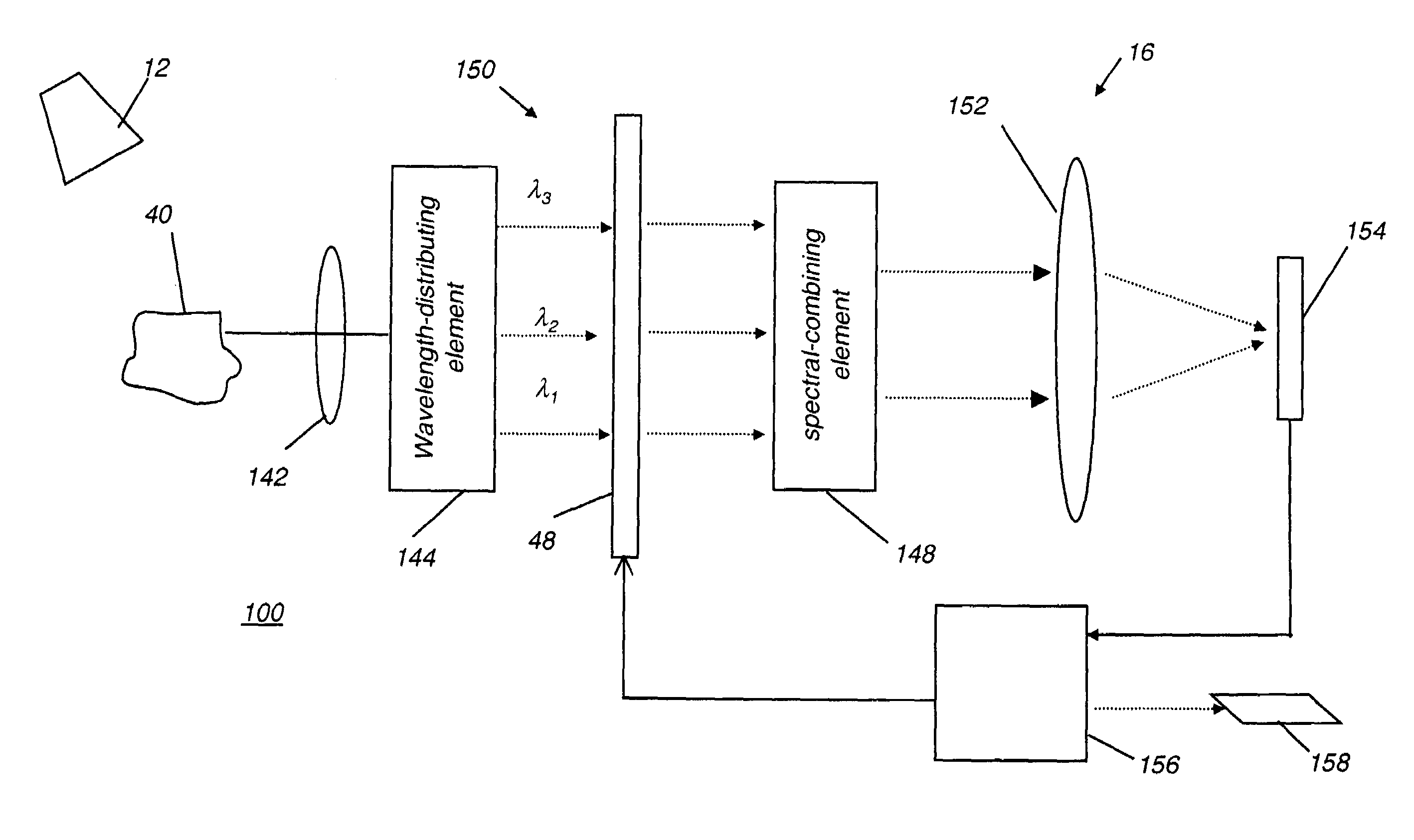
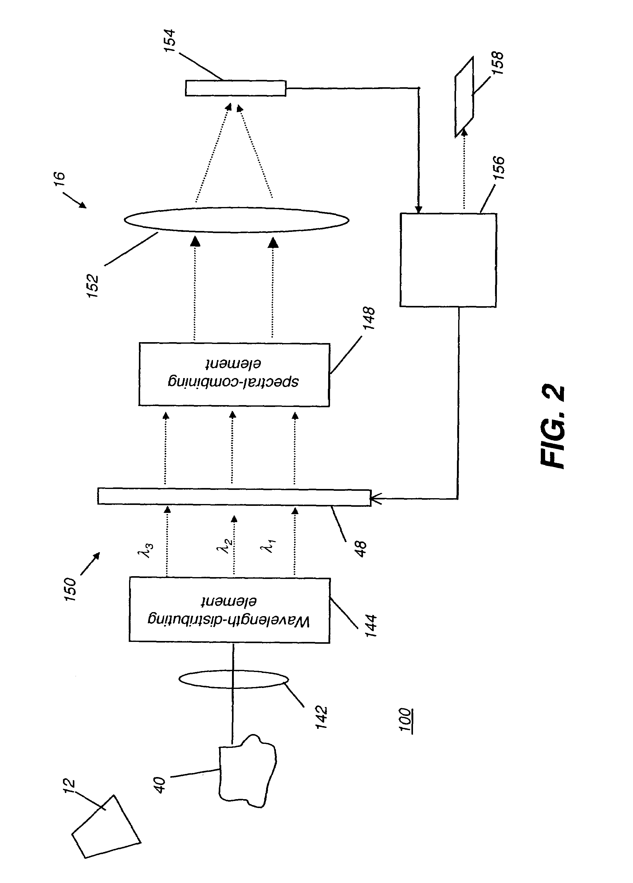
[0054]Referring to FIG. 2, there is shown a schematic block diagram of an imaging apparatus 100 according to the present invention. An extended object 40, as the object under test, receives illumination from light source 12. In spectral imager 16, a multispectral image-bearing light, from a region of interest on extended object 40, is directed toward a wavelength-distributing element 144 by a lens 142.

[0055]The multispectral image-bearing light from extended object 40 may be reflected or transmitted light having some portion of the wavelengths emitted from light source 12. Alternately, light source 12 may provide a form of excitation energy that causes an...


PUM


Abstract

An imaging apparatus for obtaining spectral image data from an object that includes: a) a light source; b) an input optics section; c) a programmable spectral filter that conditions the multispectral image bearing light according to a predetermined spectral transmission function; d) a detector array in the path of the conditioned multispectral image bearing light and providing a corresponding output signal; and, e) a control logic processor in communication with the spatial light modulator for modulating addressable areas of the spatial light modulator to provide the spectral transmission function thereby.

Description

FIELD OF THE INVENTION[0001]The invention relates generally to imaging systems and in particular to a multi-band spectral imaging system that is electronically controllable, using a wavelength-distributing element, a spatial light modulator for selection of spectral components to be imaged, and a wavelength recombining element.BACKGROUND OF THE INVENTION[0002]Multi-spectral imaging (MSI) and hyper-spectral imaging (HSI) systems, in which more than 3 spectral bands are captured by an imager, are of particular interest for a variety of applications. Originally exploited for use in aerial and satellite imaging, spectral imaging apparatus and techniques are more recently being applied to a broad range of applications where the spectral content of light yields significant information about a structure or tissue, including remote sensing, industrial sensing, and biological and health imaging. As is described in U.S. Pat. No. 5,784,162 entitled “Spectral Bio-Imaging Methods for Biological ...

Claims


Application Information

Patent Timeline
Patent Type & Authority Patents(United States)
IPC IPC(8): G01J3/28
CPCG01J3/02G01J3/0208G01J3/021G01J3/0229G01J3/0256G01J3/0262G01J3/0291G01J3/1838G01J3/2803G01J3/2823G01J2003/1282
Inventor KOWARZ, MAREK W.PATTON, DAVID L.SPOONHOWER, JOHN P.
Owner EASTMAN KODAK CO
Why Eureka
Try Eureka